When you translate a chain's effector to invoke inverse kinematics, Softimage uses a solver — an algorithm that "solves" how the effector will reach its goal by calculating how the joint angles should change. You can select both the type of solver Softimage uses, as well as the solver angle methods for calculating the joint rotations.
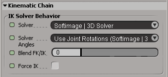
Select any chain bone and press Ctrl+R to open the Kinematic Chain property editor.
Use the Solver list to change the chain's behavior. You can use one of two solvers for a chain: the SI|3D or XSI Solver (see next section for information on choosing between the two).
Choose one of three Solver Angle methods for calculating joint rotations when using IK (see Calculating Joint Rotations with the Solver Angle for information on choosing among the three methods).
You can choose to use either the SI|3D or XSI Solver. Whichever solver you choose, it's easy to switch between them. If you find that different solvers work best for different situations on the same chain, you can even set keys on the Solver options (click its animation icon) to animate the switching from one solver to the other at specific frames.
The SI|3D Solver uses the same algorithm as in SOFTIMAGE|3D to provide compatibility with that program. If you have scenes from SOFTIMAGE|3D that you want to import into Softimage, you should use this solver to be sure that the angles are calculated the same way for your chains in both programs.
The XSI Solver uses an algorithm that usually provides quick results when translating the effector. Because the XSI solver is based on the Softimage architecture, it works better with elements that are different from (rotation limits and up-vector constraints) or didn't exist in SOFTIMAGE|3D (such as joint stiffness, pseudo-roots, and bone rolls). It knows how to stabilize and solve the chain more effectively than the SI|3D solver.
If you're working exclusively in Softimage, you may find this solver more efficient.
When you draw a chain, the angles at each joint are seen as the "home state", known as the preferred angles, of the chain. When you use IK, these preferred angles are used as an initial solution for the IK solver. Reading those angles, the solver computes a solution that depends on these angles and the goal position (as well as any up-vector or preferred axis constraints). For more information, see Preferred Angles.
Choose one of three Solver Angle methods for calculating joint rotations when using IK:
Use Joint Rotations (SI|3D Behavior) updates the preferred angles when the joint angles are changed by any means other than IK (such as by bone rotation - FK), which will affect further IK joint calculations. This is the same behavior as in SOFTIMAGE|3D, and chains imported from SOFTIMAGE|3D automatically assume this behavior. IK and FK have the same priority with this method, which means that the IK may be slightly less predictable.
If a subchain is to be solved in IK, expressions on this subchain are ignored. Otherwise, expressions take precedence over changes you make by directly manipulating the chain (transforming it), and direct manipulation changes takes precedence over fcurves (or other local orientation control).
Use Preferred Rotations from Joint Properties calculates rotation values based on the joints' preferred angles. The preferred angles in the bones stay at what you set them, meaning that the joint rotations are always predictable; a given effector position always results in the same rotation values.
IK has priority over FK with this method: FK only modifies the preferred angles of the bones, and the IK will always bend the correct way once you've set it.
The only way to stay in this joint rotation mode and change the preferred angle is to do so from the Kinematic Joint property editor (see Changing the Joint's Preferred Angle — you can see the result of doing so if Force IK is on).
Reuse Joint Rotation at Every Resolution Step ignores the preferred angles and calculates rotation values based on the joints' current angles (it keeps bending the direction that it was last bending). If you manipulate the chain in FK, and then IK, the chain won't snap back to its preferred angle. When the chain is extended to its full length, translating the effector toward the root causes the chain to bend in one direction.
Because unpredictable behavior can occur when you use IK, this method is really only practical for FK and is the option for doing "pose-to-pose" animation. Of course, you can use IK to place the chain approximately where you want, then rotate the bones (FK) and key their rotations.
Select the Force IK option on the Kinematic Chain property page to trigger IK every time you modify the preferred angles from the Kinematic Joint property page (see Changing the Joint's Preferred Angle). This way, you can immediately see the effect of IK on the chain.
Using Force IK lets you test out the effect that manipulating bones has on the IK solution without actually adding animation to or manipulating the effector.
If you select Force IK, you can temporarily force the effector to stay in place if it is not already animated. Thus, with any Solver Angles method, you can edit the preferred angles in the Kinematic Joint property editor or rotate the bones interactively.
When you're animating long chains (especially 3D chains), the error tolerance on the solver can sometimes get too large and the chain's effector may "pop" to another location. This may also be a problem when you have stiffness or rotation limits set on 3D chains.
To solve these problems, you can lower the solver's error threshold, meaning that less distortion is allowed to occur as it solves the chain's angles.
The error threshold affects only:
Lower the Threshold value until the problem stops occurring. This value is in Softimage units, with 1 being one grid square.
You need to set the Threshold value relative to the chain's length. This means that generally, the shorter the chain, the lower you need to set the value to solve any problem.
The amount that the camera is zoomed in or out of the view is also a consideration. For example, if the camera is zoomed in closely to the chain, you may need to use a very low value.
The speed at which the solver calculates the chain is affected by a combination of the chain's length and the Threshold value. As the Threshold value gets lower relative to the chain's length, the longer it takes to solve. For example, a long chain with a high value could take the same amount of time to calculate as a short chain with a low value.
 Except where otherwise noted, this work is licensed under a Creative Commons Attribution-NonCommercial-ShareAlike 3.0 Unported License


