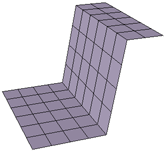
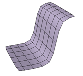
The Smooth operator is a general purpose deformation that removes spikiness and other high-frequency detail. This is very useful in many situations, for example:
Smoothing out discontinuities in the general shape of an organic object after you have tweaked it by manually moving points.
Rounding out seams where polygons were extruded, or between parts that were modeled separately and then merged into a single object.
Straightening edge loops or aligning quads so that objects deform and shade better.
There are two commands that apply different presets of the Smooth operator: Smooth affects the entire shape while Relax aligns components along the surface. In either case, you can adjust the effect further by modifying parameters as described in the sections that follow.
Smooth works by averaging the positions of points. As a result, quads tend to become squarer, triangles tend to become more equilateral, and edge loops tend to become straighter. However, you can define a custom filter with different characteristics as described in Smoothing with Custom Filters.
As an alternative to using the Smooth operator, you can use the ICE-based Smooth deformation — see Smooth.
Select the elements to be smoothed: points, edges, polygons, clusters, objects, branches, groups, or models.
Smoothing works with any geometry type: polygon meshes, NURBS surfaces, NURBS curves, lattices, hair, and particles. However, note that:
With particles, you must define a custom filter with a Distance type of Spatial (ignore neighborhood). For more information, see Smoothing with Custom Filters.
With NURBS surfaces, closed boundaries are treated as if they were connected. However, boundaries between subsurfaces in assembled surface meshes are not considered connected.
Choose one of the following commands from the Model, Animate, or Simulate toolbars:
Modify  Deform Smooth. This preset is a good starting point if you want to smooth the overall shape.
Modify Deform Relax. This preset is a good starting point if you want to align components without affecting the silhouette as much.
The Smooth Property Editor opens.
Adjust the parameters as described in the sections that follow.
Controlling the Amount of Smoothing
You can set the strength of the smoothing effect directly, as well as extrapolate the displacement of points, as described next. In addition, you can control the strength near unsmoothed areas using a falloff (see Creating a Falloff Between Smoothed and Unsmoothed Areas) and set a minimal displacement (see Setting a Minimal Displacement).
Controlling the Strength Directly
Strength on the General tab of the Smooth property editor controls the amount of smoothing. It represents the number of iterations that each point's position is averaged with its neighbors' positions. Decimal values interpolate between whole iterations.
You can also use a parameter map by right-clicking on the connection icon. For example, you can use a weight map and paint weights to differentiate between areas where you want more or less smoothing to occur. For more information about using parameter maps to control values in general, see Parameter Maps.
Extrapolating the Displacement
Extrapolation on the Advanced Settings tab of the Smooth property editor exaggerates the displacement of each point. Positive values move the points in the same direction as the smoothing, and negative values move points in the opposite direction.
While you can achieve some interesting effects with this parameter, it is particularly valuable as a diagnostic tool: you can temporarily adjust it to see what areas are being most affected by smoothing, and then set it back to 0.
Preserving Features While Smoothing
You can protect vertices that meet specific criteria from being smoothed. You can also control whether unselected vertices are considered when calculating average positions, as well as create a falloff between unsmoothed and smoothed areas.
Protecting Vertices that Meet Specific Criteria
The options under Feature Preservation on the General tab of the Smooth property editor protect vertices that meet the corresponding criteria:
Boundary vertices prevents points on boundary edges from being smoothed. Because boundary edges have neighbors on only one side, they are often pulled strongly in that direction when positions are averaged. This option prevents things like mouths and eyes from becoming distorted by smoothing. It can also help when smoothing assembled surface meshes, because the boundaries of the subsurfaces are not considered connected.
Hard edges/vertices prevents points and edges that have been marked as hard (using Modify Component Mark Hard Edge/Vertex) from being smoothed.
Crease edges/vertices prevents points and edges with crease values set (using Modify Component Set Edge/Vertex Crease Value) from being smoothed.
When any of these options are on, you can create a falloff from the protected vertices as described in Creating a Falloff Between Smoothed and Unsmoothed Areas below.
Controlling Whether Unselected Vertices Are Considered
When you smooth a selected portion of an object, Consider unselected vertices on the General tab of the Smooth property editor controls whether the vertices in the unselected (unsmoothed) area are considered when average positions are calculated.
When this option is on, all of a point's neighbors are considered when the average position is calculated. This allows for a transition at the borders of the smoothed region. You can refine this transition further by creating a falloff as described in the next section, Creating a Falloff Between Smoothed and Unsmoothed Areas.
When this option is off, only other selected vertices are considered when calculating average positions. As a result, the selected area is smoothed as if it was disconnected from the rest of the geometry.
Creating a Falloff Between Smoothed and Unsmoothed Areas
If you applied the smooth operator to specific components or clusters, the options under Falloff on the General tab of the Smooth property editor allow you to create a gradual transition between the smoothed and unsmoothed areas.
Radius represents how far the falloff area extends into the smoothed region from its borders.
By default, values are in terms of the neighborhood, where 1 represents points that are immediately adjacent to the border of the unsmoothed area, 2 represents points that are one point away from the border, and so on. Values between whole numbers are interpolated.
If you are using a custom filter, values are in terms of the distance type you set.
Sharpness controls the shape of the transition in the falloff region. Low values produce an abrupt transition at the beginning of the falloff region (near the unsmoothed areas) and high values produce an abrupt transition near the end of the falloff region. Moderate values produce a smooth transition spread out over the whole falloff region.
Adjust both sliders to achieve the desired falloff profile. If either slider is 0, there is no falloff at all.
The falloff options are unavailable unless at least one of the options above them (Boundary vertices, Hard edges/vertices, Crease edges/vertices, or Consider unselected points) is active.
Aligning Components, or Preserving the Shape While Smoothing
Because smoothing works by averaging the positions of vertices, objects tend to shrink. There are a couple of ways to minimize the shrinkage. Both of these methods tend to align components along the surface rather than smooth sharp details.
Reproject on the Advanced Settings tab of the Smooth property editor projects each point back onto the surface of the unsmoothed geometry. As a result, the components become aligned in surface space but the object does not shrink as much. However, the reprojection may miss some spiky details, so the object's shape may still be smoothed down somewhat even when this option is on.
Setting Restrict to normal direction to Perpendicular on the Advanced Settings tab of the Smooth property editor prevents each point from being displaced along its normal (local Y) and restricts the movement to its local X and Z. This option is better than Reproject at keeping sharp details, but is less good at aligning components in surface space.
Restricting the Smoothing Effect
Several options on the Advanced Settings tab of the Smooth property editor allow you to restrict the smoothing effect.
Restricting the Effect by Curvature
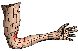
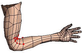
Restrict to curvature type on the Advanced Settings tab of the Smooth property editor lets you restrict the smoothing effect based on the local curvature: concave or convex, as determined by the geometric normals (user-defined normals are not considered).
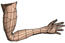
For example, you can smooth concavities to eliminate pinching that may occur in elbows and other regions:
Restricting According to Normals
Restrict to normal direction on the Advanced Settings tab of the Smooth property editor controls the direction in which points are displaced:
None allows points to be displaced in any direction without restriction.
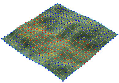
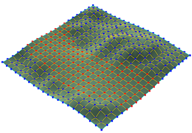
Parallel allows points to move only in the direction of their normals (local Y axis). This can be useful, for example, if you want to smooth the height of terrain without affecting the alignment of the map grid or roads.
Perpendicular allows points to move only in the direction of their local X and Z axes. This can be useful for aligning components along the surface without smoothing protuberances and indentations. See Aligning Components, or Preserving the Shape While Smoothing.
Setting a Minimal Displacement
Minimum displacement on the Advanced Settings tab of the Smooth property editor is a clamp that sets the minimum distance that a point will be moved. If the difference between a point's current position and the average position of its neighbors is less than this amount, the point is not moved. This allows you to smooth noisy areas of an object without affecting areas that are already smooth enough. Values are in Softimage units.
Specifying the Smooth Direction
The Restrict Direction options allow you to specify a particular direction for the smoothing effect. Activate Enable, and then specify a vector using X, Y, and Z. The displacement is calculated according to the other options, and then projected onto the direction specified. The X, Y, and Z values are automatically normalized so the displacement is not scaled; use Extrapolation if you want to scale the displacement.
The Custom Filter tab of the Smooth property editor allows you to specify a different algorithm than the default smoothing. With a custom filter, each point's position is still being averaged with the positions of nearby points. However, you can control:
The criterion, or distance type, used to measure the distance between points.
The maximum distance with respect to that criterion for a point to be considered "nearby".
A profile curve that weights the average over the distance used.
All the other options on the General and Advanced Settings tabs of the Smooth property editor work in conjunction with custom filters.
Setting the Distance Type, Distance, and Computation Limits
Distance type on the Custom Filter tab of the Smooth property editor determines the criterion used to measure the distance between points, and Distance determines how far away "nearby" points can be.
No matter which distance type you choose, large distance values can cause long computation times because the operator evaluates many nearby points. The Computation limit options are a "safety valve" that prevent excessively long calculations that may occur if you set values that result in enormous numbers of points being considered "nearby" to each other. If the computation limit is too high, it may result in long computation times when Distance is also high, but if the computation limit is too low, it may prevent the Smooth operator from evaluating all nearby points.
A Distance type of Neighborhood uses connectivity as a measure of distance. This is the same distance type used by the default smoothing algorithm, but the custom settings give you greater control over the distance and profile.
The Distance between two points is the least number of edges in any path between them. Thus, adjacent points have a distance of 1, points that are separated by two edges have a distance of 2, and so on. Even though points are always separated by a whole number of edges, you can still use decimal values for the distance; values between whole numbers are interpolated, so a distance of 1.5 yields a displacement halfway between the displacements achieved by distances of 1 and 2.
A characteristic of this distance type is that edge lengths tend to become equal at high Strength values.
A Distance type of Edge Path Length uses the sum of the edge lengths in the shortest path between two points as the measure of distance. Distance values are in Softimage units.
A useful characteristic of this distance type is that the ratio of edge lengths is maintained, even at high Strength values.
Use Max neighborhood depth to prevent excessive calculations.
A Distance type of Spatial (consider neighborhood) uses the distance between points in 3D space, as long as the points are connected by edge paths. Distance values are in Softimage units.
Use Max neighborhood depth to prevent excessive calculations.
A Distance type of Spatial (ignore neighborhood) uses the distance between points in 3D space, whether or not the points are connected. The Distance values are in Softimage units.
This is the only distance type that can be used with particles, since the points in a particle cloud are not connected. This distance type is also useful for hair because only points on the same guide hair are connected.
The Smooth profile is a graph that controls how the positions of nearby points are weighted as a function of distance. The horizontal axis represents the distance of a nearby point, where 100 is the maximum distance set by the Distance slider. The vertical axis represents how strongly points at the corresponding distance are weighted when calculating the average position. Positive values pull a point towards its neighbors, and negative values repel it.
You can select the profile curve and edit it using the mouse and the same keyboard commands as the fcurve editor, or right-click to display a menu.
For more information about editing curves in general, see Editing Function Curves [Animation].