


Inputting and Outputting
with Headroom
With 4:2:2 serial digital interface (SDI) input and output connections, the colour components of video signals are Y (luma), Cb (blue colour difference), and Cr (red colour difference). For standard video signals in 10 bits, black has a luma value of 64 and white has a luma value of 940. When performing standard captures to RGB values on Backdraft Conform systems, black YCbCr (64,512,512) maps to RGB (0,0,0) and white YCbCr (940,512,512) maps to RGB (1023,1023,1023). SDI values 0 to 3 and 1020 to 1023 are reserved values for synchronization purposes.
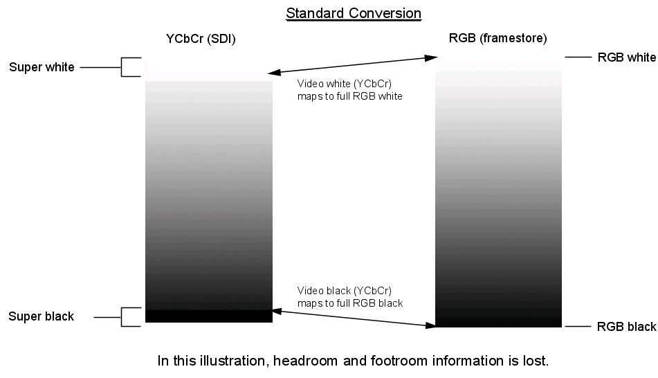
Some cameras record shadow details below the video luma black value of 64 and white detail above the video luma white value of 940. These details are called super blacks and super whites. These are also referred to as “headroom” and “footroom.” Under normal circumstances, headroom is not converted during capture, and the super black and super white details are lost, as described in the following illustration:


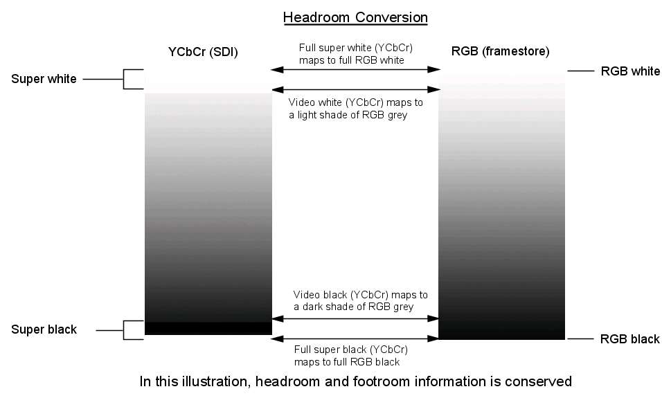
Using the YCbCr<->RGB with headroom colour space option during input on Backdraft Conform systems, it is possible to capture these super black and super white values. In this case, video black YCbCr (64,512,512) maps to RGB (64,64,64) in 10 bits, and video white YCbCr (940,512,512) maps to RGB (940,940,940). YCbCr Luma values between 4 and 64 and between 940 and 1019 are converted to RGB on capture. While this gives you the advantage of being able to capture super black and super white values, it also means that video black will not map to full black in RGB, and video white will not map to full white in RGB. The following image illustrates this:
For 4:4:4 RGB standard input and output, a similar explanation applies. On capture using the No Conversion setting, RGB 4:4:4 SDI video black at value (64,64,64) maps to RGB (0,0,0), and RGB 4:4:4 SDI video white at value (940,940,940) maps to RGB (1023,1023,1023).
With the No Conversion with Headroom option, the maximum possible SDI value range is used. RGB 4:4:4 SDI values ranging from (4,4,4) to (1019,1019,1019) map to the same RGB range on capture.
Although the preceding descriptions relate to capture from SDI to the framestore, the reverse applies when outputting from the framestore to SDI.
To enable colour space conversion on clip input:
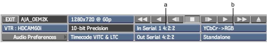
(a) Input Connection box (b) Colour Space box
To enable colour space conversion on clip output: