Part 5: Finish the model


Category New Users
Time Required 20 minutes
Tutorial File Used vacuum_part4.wire (completed in the Modify the model with history lesson)

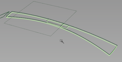
With the basic exterior shape and handle established, you can create transition surfaces and fine details to finish the model.

Objectives

Prerequisites

Watch Video

Enclose the handle and create transition surfaces

The main body of the vacuum can be enclosed and rounded at the edges.

  1. Make the layers handlesurfaces, topsurfaces, and frontsurfaces visible, and toggle the visibility of all other layers.
  2. Make the frontsurfaces layer active.
  3. Choose SurfacesPrimitivesPlane.
  4. In the Top view, use grid snap to position the plane under the handle region.
  5. Choose Surface EditProject and click the bottom edges of the handle region surfaces.
  6. Type Z and press Enter to set the projection direction.
  7. Click the Project button.
  8. Choose Surface EditTrim and pick the plane.
  9. Click in the exterior edge of the plane, and Click the Discard button.
  10. Choose SurfacesSurface Fillet and open the tool options.
  11. Set the Section Type to G2 Curvature, and the Center radius to 10.
  12. In the Flow Control section, set Start and End to Edge align.
  13. Pick the back rail surface and click Accept.
  14. Pick the adjacent top surface and click Accept.
  15. Verify that the build direction arrows are facing inward.
  16. Click the Build button.
  17. Toggle Shade (Fast) on and examine the surfaces.

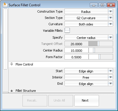
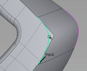
    The fillet surface has curvature continuity, as if the top and back edges are a single continuous surface.

Align and trim edges

To create a transition surface between the fillet and the square, they must be aligned and trimmed.

  1. While the fillet is still selected, click the Look At button in the NavBar to zoom into the surface.

    The fillet surface extends beyond the square surface.

  2. Choose Object EditAlign and open the options box.
  3. Change the Alignment Type to Project, and the Vector to Y.
  4. Pick the edge of the surface fillet nearest to the square surface, and confirm that construction history will be removed.
  5. Click the interior of the square surface to set it as the master geometry.

    The edge of the fillet surface aligns with the square surface, and curves-on-surface are created.

  6. Choose Surface EditTrim and pick the square surface.
  7. Click in the interior of the square, and Click the Keep button.

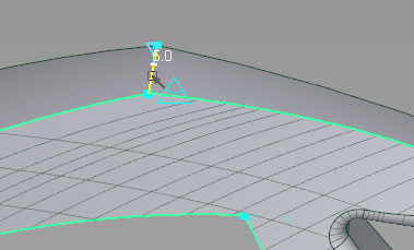
Round the edges and set corner shapes

The Round tool automatically creates transition surfaces at edges and corners. This can complete the transition between the top and side surfaces
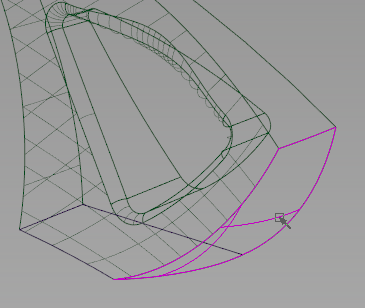
  1. Choose SurfacesRound.
  2. Click the top edge to set a Round Radius.

    A radius locator appears where you click, and the edge is set to be rounded.

  3. Type a value of 5 for the default radius, and press Enter.
  4. Continue to click all the edges around the square side, as shown in the following image.
  5. Click the Build button to see the transition surfaces.

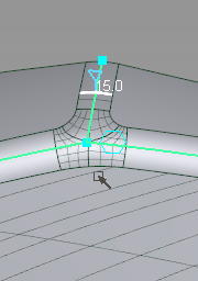
    There is an error at the back corner, where a round surface is not trimming.

  6. Click the Revert button to return to edge selection.
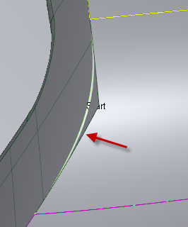
  7. + click the area to set the center of interest, then Zoom into the blue square at the back corner.

    Blue squares indicate corners or tangent breaks. There is a break along this edge.

  8. Click to add a radius on the edge in between the two blue squares.
  9. Click the Build button to see if the error is resolved, then click the Revert button to return to pick more edges.
  10. Click to add a radius on the edge between the top surfaces.
  11. Type a new radius value of 15 and press Enter.
  12. The corner where the three edges meet has a hexagonal Corner shape manipulator next to it.

    This indicates a multi-surface setback corner.

  13. Click the Build button to see the surfaces.
  14. Click the Corner shape manipulator to change it to a rectangle (single surface corner).
  15. Click the Build button to see the desired single surface.
  16. Click the Revert button to return to edge selection.
  17. Toggle Shade (Fast) OFF to see the interior wireframe edges.
  18. Give the 3 remaining edges of the vacuum housing a radius of 15 each, and set their corner shapes to single surface as well.
  19. Click the Build button to see the desired round on all visible edges.
  20. Toggle Shade ON on to inspect the shape of the transition surfaces.
  21. FileSave the model as vacuum_part5.wire.

Round the motor box

  1. Set the state of layers handlesurfaces, topsurfaces, and frontsurfaces to Reference.
  2. Make the layer motorsurfaces visible and active.
  3. Toggle Shade OFF to see the wireframe edges.
  4. Choose SurfacesRound.
  5. Click on the back edge of the motor box.
  6. Set the radius to 15.
  7. Click all other edges of the motor box to add radii of 15 to them.
  8. Set the two corners to be multi-surface setbacks (hexagon manipulators).
  9. Toggle Shade ON to inspect the shape of the transition surfaces.
  10. Click the Build button to see the surfaces.
  11. Set the state of layers handlesurfaces, topsurfaces, and frontsurfaces to Pickable.
  12. Turn on Symmetry for the visible layers, and inspect the model.
  13. Pick Nothing.
  14. -click the layer motorbox and choose Pick Objects.

    With this new, history-based motorbox, the early reference geometry and layer are no longer needed.

  15. Delete the old motorbox geometry.
  16. While the layer motorbox is the only active layer, choose LayersDeleteSelected Layers.

Create a power switch

A custom construction plane will assist in creating the small detail of the power switch on top.

  1. Hide the layers motorsurfaces, handlesurfaces, and frontsurfaces.
  2. Make the layer imageref visible.
  3. Make the layer topsurfaces the active layer.
  4. Toggle Shade OFF to see the wireframe edges.
  5. Choose ConstructionPlane.
  6. Click the Geom button, to align the new construction plane to scene geometry.
  7. Click-drag the top surface until the center of the plane is centered on the sketch switch.
    NoteThe orientation of construction planes varies with the geometry you align to. If the plane is not as shown above, click the black square manipulators to set the plane to the right axis.
  8. Click the Set Construction Plane button. The coordinate system is set to this plane.
  9. Use the ViewCube to switch to the Right view.

    You can see that the ViewCube axes are "tilted" to the active construction plane axes.

  10. Switch to the Top view.
    NoteThe sketches may appear incorrect because we are viewing them at an angle in orthographic views.
  11. Choose SurfacePrimitivePlane, and grid-snap the plane along the centerline until it is centered at the thinnest part of the top surface.
  12. Use the Scale manipulators on the plane to adjust its size to fit inside the top surface, as shown in the following image.
  13. Choose Curve EditDuplicate Curve, and click the three edges of the plane.
  14. Pick Nothing, and then Pick Object and pick the plane.
  15. Delete the plane.
  16. Choose Curve Edit
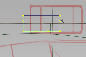
Fillet Curve, and pick two intersecting curves.
  17. Enter a radius of 3, and click Accept.
  18. Add a similar Fillet Curve with a radius of 3 in the opposite corner.
  19. Pick Object, and pick all 5 curve segments.
  20. Switch to the Perspective view, and see that they are drawn directly on the construction plane.
  21. Create a New Layer, rename it switchcurves and Assign these curves to it.
  22. FileSave the model as vacuum_part5.wire.

Create the switch emboss

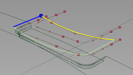
A construction vector will aid in creating an embossed region for the switch to slide in.

  1. Hide the imageref layer.
  2. Choose ConstructionVector.
  3. -click to start the vector on the construction plane.
  4. Click the blue vector line to set the vector perpendicular to the construction plane.
  5. Choose Surface EditProject, and pick the top surface to project onto.
  6. Click the vector to set the projection direction.
  7. Click Go, and pick the 5 filleted curve segments.
  8. Click Project.
  9. Make a new active layer named switchsurfaces, then hide the switchcurves layer.
  10. Choose Object Edit
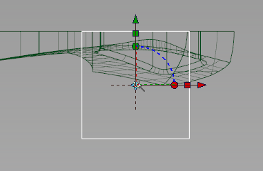
Offset, and pick the top surface. An offset preview appears.
  11. Click the direction vector to reverse it so that the offset is going toward the inside of the vacuum.
  12. Enter an offset distance of 2, and press Enter.
  13. Click Offset to calculate the surface. An offset copy of the top surface is placed 2 mm below the original.
  14. Choose Surface EditTrimTrim Surfaces, and pick the offset surface. Click to define the exterior and click Discard.
  15. While the Trim tool is still active, pick the original top surface.
  16. Click to define the exterior, and click Keep. There is an offset cut-out below the original top surface.
  17. Choose SurfacesRolled EdgeFillet Flange and open the options.
  18. In the Fillet Flange Control option box, check on Auto Trim and Chain Select.
  19. Set the Fillet Radius to 1, and the Flange Length to 1.
  20. Zoom into the switch location on the top surface, and pick the trim edge.
  21. Check the direction of the flange and fillet. If pointed up, check the Fillet Flange Wall option to Flip.
  22. Click Recalc to build the fillet flange.
  23. FileSave the model as vacuum_part5.wire.

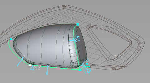
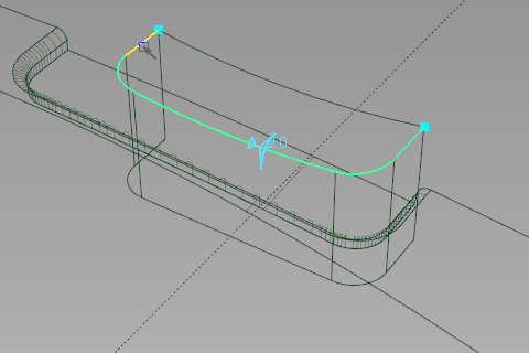
Create the switch curves and surfaces

Some objects from the previous step can be copied and modified with history to create the shape of the switch inside the embossed region.

  1. Make the switchcurves layer visible and active, and hide the switchsurfaces layer.
  2. Pick Curves and select the 5 curves of the switch profile.
  3. Copy and Paste duplicates into the scene.
  4. -click the fillet curves in each corner to unpick them. A pick chooser appears with the copied fillet checked in the list.
  5. In the Right view, Move the remaining 3 copied curves using the .

    The fillets move with them.

  6. Choose Transform LocalSet Pivot and magnet snap the pivot to a CV on the selected curve near the back.
  7. Choose TransformNon-proportional Scale.
  8. Enter values of 0.7, 1, 1 (with commas) and press Return, to scale the curves by 70% in the X direction, and maintain 100% in the Y and Z directions.
    NoteIf the active construction plane has different axes from what is shown in the tutorial, the order of these values (X, Y, Z axis, respectively) may change.

    Again, the curve segments adjust to these dimensions, but the fillet curves retain their radii.

  9. Choose CurvesNew Edit Point Curve, and in the Right view, draw an arc between the copied curves and the originals.

    This becomes the top of the switch button.

  10. Make the switchsurfaces layer visible and active.
  11. Choose SurfacesDraft SurfacesMulti-surface Draft and open the option box.
  12. In the Multi-surface Draft option box, under Pick Mask, uncheck all components except Curves.
  13. Pick the curved profile as the input curve, and set the Draft Vector to be Y and length to be 12.
  14. Click Recalc to build the draft.
    NoteIf needed, check the Flip option to keep the draft on the modeling side of the symmetric plane.
  15. Click the Next button in the option box.
  16. In the Control option box, check Chain Select.
  17. Pick the copied profile curves.
  18. Click the construction vector to set the draft direction.
  19. In the Multi-surface Draft option box, set the Length to be long enough to intersect the embossed area.
  20. Click Recalc to build the second draft.

Intersect, trim, and round the switch

With the initial surfaces created, the switch volume can be trimmed out and rounded.

  1. Choose Surface EditIntersect while the second draft is still picked.
  2. Pick the curved draft surface to intersect with.
  3. Make the imageref layer visible and pickable.
  4. Pick the Left view sketch canvas (Canvas-2) to intersect with.
  5. Hide the imageref layer and make it reference again.
  6. Hide the switchcurves layer.
  7. Choose Surface EditTrimTrim Surfaces.
  8. Use + to pick all of the draft surfaces (the top and all 5 side surfaces) to trim.
    NoteThis is easiest when picking the side surfaces where they extend under the emboss region.
  9. Click to define the interior regions of the draft surfaces.
    NoteThe back part of the vertical draft should be selected closest to the filleted corners.
  10. Click Keep.
  11. Choose SurfacesRound.
  12. Click the upper edge of the switch and set the radius to 2.
  13. Continue selecting edges all along the top of the switch.
  14. Click Build.
  15. Turn on symmetry for the topsurfaces and switchsurfaces layers and examine the results in Shaded (fast) view.
  16. If needed, adjust the height or shape of the button top to make a lower profile switch.
  17. Choose ConstructionToggle Construction Plane to return to the main axes.
  18. FileSave the model as vacuum_part5.wire.