| Category | New Users |
| Time Required | 20 minutes |
| Tutorial File Used | vacuum_part5.wire (completed in the Finish the model lesson) |
Once the vacuum is fully modeled, it can be rendered with realistic shaders and lighting to show how it would look when produced. This lesson focuses on shading and lighting your model realistically, and producing image output to share the visuals.
The model has been created as one half of a symmetric design, and the other half of the model must "exist" for data sharing.
 +
+ -click to select the symmetric layers.
 SymmetryCreate Geometry.
This converts the symmetric display geometry into real geometry and disables layer symmetry.
Save the model as vacuum_visualize.wire to avoid overwriting the modeling geometry file.
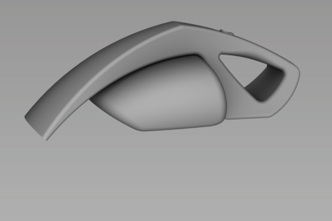
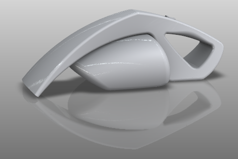
Shade the model with hardware shading
Interactive hardware shading can produce stunning visual results with the correct settings.
Hardware Shade and open the option box.
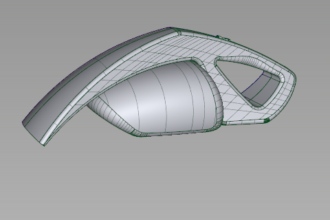
How your objects are shaded depends on the last settings in your Hardware Shade dialog.
 + +
+ +  to see the Display marking menu, and select Shade (Fast).
The marking menu entry is a preset toggle, and changes the hardware shade options to reflect a fast rendering type.
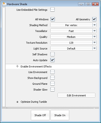
Compare both how the model looks and what options have changed in the dialog.

Your interactive performance in hardware shade is dependent on your video card and drivers. If you experience lags or problems, check the system requirements.

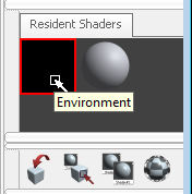
The number of tabs visible depends on the size of the user interface.
Only one environment preset can be active in the scene at a time, so double-clicking an environment replaces the current one entirely.
 TogglesWindow Display Window DisplayModel to hide the wireframe but continue showing the shaded surfaces.
Anti-AliasShaded Anti-Alias and open the option box.
TogglesWindow Display Window DisplayModel to hide the wireframe but continue showing the shaded surfaces.
Anti-AliasShaded Anti-Alias and open the option box.
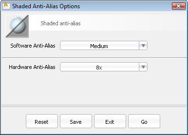
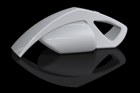
The display is visually smoother, but interactive performance could be reduced. Toggle Shaded Anti-Alias off if the screen refresh is too slow.
 Save the model as vacuum_visualize.wire.
The current Hardware Shade options are saved with the file. However, when starting a new session of Alias these options return to their defaults. To return to the file-specific settings, check Use Embedded File Settings at the top of the Hardware Shade option box.
Ambient Occlusion is a form of shading that adds depth to a model by simulating the shadows from light that surrounds the objects. Ambient Occlusion in Alias is "baked" to the geometry as textures, so it can be used in hardware and software rendering with no performance difference.
Ambient OcclusionCompute and open the option box.
The shading changes to a blue and yellow "surface normals" display.
 -click a yellow surface to reverse its direction to face the camera.
a selection box around multiple surfaces to set them all to face the camera.
-click a yellow surface to reverse its direction to face the camera.
a selection box around multiple surfaces to set them all to face the camera. 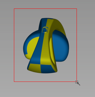
Continue to zoom and tumble to examine the model for yellow surfaces facing outward.
 Save the model as vacuum_visualize.wire.
Edit the background and lighting
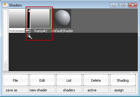
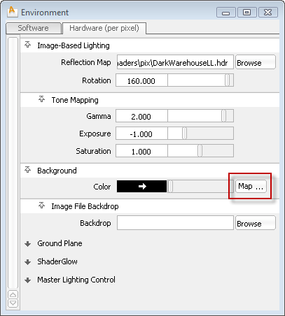 Surface section, click the Ramp shader button.
A procedural Ramp shader is applied to the visible background, and the Ramp editor opens.
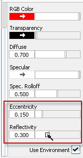
 -click the check box to the right of the red ramp color section to delete this color.


 Multi-listerLights to see the editable lights in the scene.


The Ramp shader that is a component of the Environment becomes hidden.

The hardware ground plane shadow links to the direction of the lights in the scene.
Save the model as vacuum_visualize.wire.
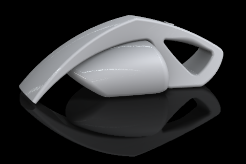
Apply preset and custom shaders
Theses steps shade the model for final presentation. After following the steps below to learn how to apply and modify shaders, you can use any colors or materials desired.
 , click-drag the Plastic_Smooth_Red shader onto the vacuum model in the scene window.
This method of applying shaders replaces the target shader on every surface it is applied to in the scene. The entire vacuum had the Default shader applied, so all surfaces are replaced with the red plastic.
With these shaders in the Resident Shader list, we can start applying them.
Apply Shaders.
The mouse buttons now support the Apply Shaders tool, and the cursor changes to describe the current action.
 -click in the workspace to bring up the Shader Assign hotspot, and drag to the left to select Assign by Layer.
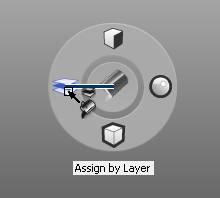
The cursor changes to the Assign Shader paint bucket with the layers symbol above it.
-click the motorbox to apply the shader to it. 
This Shader Assignment affects all surfaces in the layer motorsurfaces.
-click to assign the Grey_Textured shader to it.
-click in the workspace to bring up the Shader Tool hotspot, and drag to the right to select Open Shader Editor.  -click the button geometry to open the editor for the Plastic_Dark_Grey_Textured_Fine shader.
-click in the workspace to bring up the Shader Tool hotspot, and drag down to select Duplicate Shader.
-click the button geometry to open the editor for the Plastic_Dark_Grey_Textured_Fine shader.
-click in the workspace to bring up the Shader Tool hotspot, and drag down to select Duplicate Shader.  -click the button geometry to copy the Plastic_Dark_Grey_Textured_Fine shader.
-click and drag up to change the Shader Assign mode to Assign by Component.
-click the button geometry to copy the Plastic_Dark_Grey_Textured_Fine shader.
-click and drag up to change the Shader Assign mode to Assign by Component.  -click the inner handle-grip surfaces on both sides of the vacuum.
 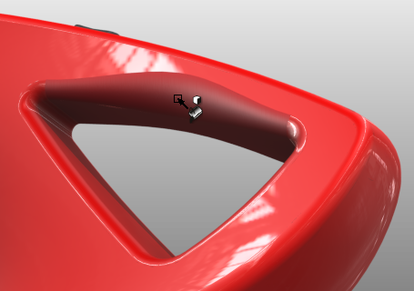 Save the model as vacuum_visualize.wire.
Set and publish bookmarks of camera views
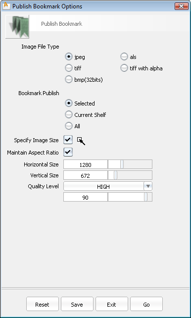
Bookmarks save the current camera position and center-of-interest, as well as the viewing options (shaded view, model visible, etc.) for quick access later on. Bookmarks can also be published to render images of your scene to disk.
and  (or and
  on the Mac), to show the NavBar under the ViewCube.
  and (also and on the Mac) still held down, find the Bookmarks section at the bottom of the NavBar.

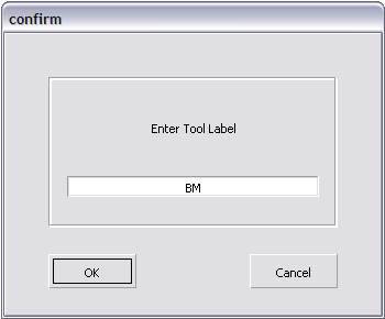
A new bookmark appears in the bookmarks list at the bottom NavBar bookmarks menu.
The view switches back and forth between the two bookmarked views.
Bookmark Lister.
The Bookmark Lister window appears.

Note the tool buttons in the Bookmark Lister window:
in an empty part of the Bookmark Lister, and choosing New shelf from the drop down menu creates a shelf.
(Windows) or  (Mac) key and double-click the first bookmark icon in the Bookmark Lister.
 (Windows) or (Mac) double-click and rename any other bookmarks.
 Save the model as vacuum_visualize.wire.


