| Category | New Users |
| Time Required | 20 minutes |
| Tutorial File Used | vacuum_part3.wire (updated in the Create and evaluate surfaces lesson) |
In this lesson you define and enclose the vacuum shapes with advanced surfaces and trims, and modify the shape of those volumes.
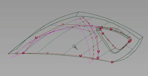
First create the side surface for the handle from the existing surfaces and a new curve.
 New CurvesNew Edit Point Curve
 .
.
 +
+ +
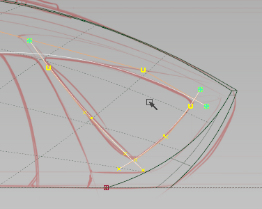
+ and drag to curve snap the first edit point to the bottom trim edge of the back surface.
Pick CV
and drag to curve snap the first edit point to the bottom trim edge of the back surface.
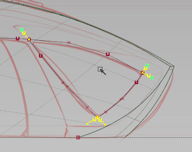
Pick CV , and drag-select the interior CVs of the new curve.
Move
, and drag-select the interior CVs of the new curve.
Move , and
, and  -drag the CVs along the Y axis, toward the centerline.
You can create the side surface for the vacuum from the region that these three surfaces and the curve define.
Boundary SurfaceSquare Surface , and open the options box.
 to examine all of the surfaces.
Evaluate and simplify the surface with History
The number of surface spans is excessive, and can cause problems in later modeling operations.
Query Edit .
on the square surface. The options for the tool that created the surface are opened, and you can modify the surface parameters interactively.
.
on the square surface. The options for the tool that created the surface are opened, and you can modify the surface parameters interactively.
Locators are created where the surface touches another surface.
A green "P" indicates the surfaces touch each other along that edge within the set tolerances.
The number of spans are reduced as each boundary is rebuilt, and continuity is maintained.
Locators to remove the continuity display.
Save
to remove the continuity display.
Save the model as vacuum_part4.wire.
Create the interior of the handle
New CurvesNew Edit Point Curve.
CutIntersect Curves and Detach.
Delete Active.
Fillet Curves .
-click-drag to adjust the radius to match the sketch, or type a precise radius amount.
Save the model as vacuum_part4.wire.
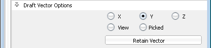
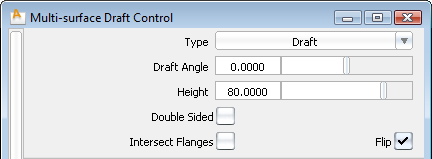
Draft SurfacesMulti-surface Draft
.
-click-drag to adjust the radius to match the sketch, or type a precise radius amount.
Save the model as vacuum_part4.wire.
Draft SurfacesMulti-surface Draft and open the options box.
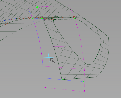
Create transition surfaces for the handle
Create transition surfaces to blend surfaces that flow in different directions, like the side of the vacuum and the interior handle surfaces.
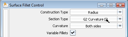
Multi-Surface FilletSurface Fillet .
.
Two arrows appear to indicate the normal direction of the Surface Fillet for each set of surfaces.
The directions are outward for the Draft surfaces, and inward to the centerline for the Square.
The Fillet surfaces are built around the edge of the intersection, but you can adjust the radius.
to examine the transition surfaces.
Construction History allows for complex surfaces to be updated, even long after they have been built.
Query Edit.
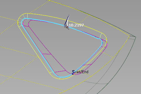
-click any of the Surface Fillet surfaces.
-click-drag near the center of the top edge to create a radius with a value near 10.
A new fillet is created with a variable radius, however this radius is not easily controlled.
User Defined Texture and tumble the view to examine the reflections along the transition.
New CurvesNew Edit Point Curve.
Draft SurfacesMulti-surface Draft and open the options.
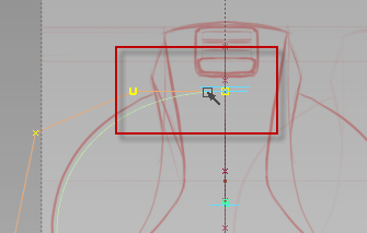
 Create CurvesOnSurfaceIntersect
 .
.
Curves-on-surface are created only on the draft surfaces where the canvas plane intersects them.
Hide Unselected to isolate these items in our workspace.  TrimTrim Surface
 and pick the Square surface as input.

 Create CurvesOnSurfaceIntersect and pick the front draft surface to intersect with.
TrimTrim Surface and pick the back draft surface as input.
Create CurvesOnSurfaceIntersect and pick the front draft surface to intersect with.
TrimTrim Surface and pick the back draft surface as input.
 Visible
 to display the other objects in the scene.
Save the model as vacuum_part4.wire.
to display the other objects in the scene.
Save the model as vacuum_part4.wire.
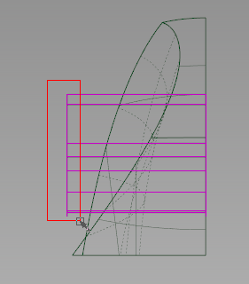
Draw the final motor box profiles
Our initial motor box and waste bin helped us to judge the volume, but now we will follow the sketch for profiles.
If the layers in the Layer Bar are disappearing on the left side, click and drag on the Layer Bar scroll icon to make them visible again, or choose WindowsObject Lister and then choose LayersToggle Layer Bar to hide the Layer Bar.
 PrimitivesCircle
 and open the option box for the tool.
 ModifyTransform Curve
 .
AlignSymmetry Plane Align
.
AlignSymmetry Plane Align .
New CurvesNew Edit Point Curve.
Draft SurfacesMulti-surface Draft.
Hide Unselected
.
New CurvesNew Edit Point Curve.
Draft SurfacesMulti-surface Draft.
Hide Unselected .
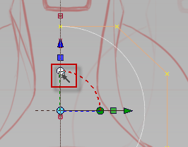
LocalSet Pivot
.
LocalSet Pivot and magnet snap the pivot to the top CV of the circle.
Copy
and magnet snap the pivot to the top CV of the circle.
Copy the circle, and EditPaste
 a copy into the scene.
The copy is placed exactly over the original, so only Paste once.
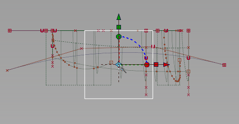
Move (+ M) and curve snap the copy to the top corner of the draft surface.
Scale and scale the curve to about 55% of its original size.
Paste a second copy of the larger circle into the scene.
Visible to bring back the contents of the visible layers.
until it is near the handle region.
and scale the curve to about 55% of its original size.
Paste a second copy of the larger circle into the scene.
Visible to bring back the contents of the visible layers.
until it is near the handle region. 
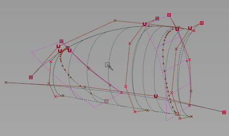
The skin tool can create a controlled surface from a few carefully positioned curves.
 Hide Unselected.
Skin
Hide Unselected.
Skin and Shift-pick each circle from back to front.
 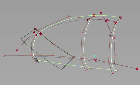 AlignAlign
 , and pick the top edge of the skin surface.


 AlignSymmetry Plane Align and pick the same top edge of the skin surface from the pick chooser.
  Save the model as vacuum_part4.wire.
Intersect and trim the surfaces
Query Edit and pick the small draft surface.

The second profile is added to the draft, and a second surface is created.
Create CurvesOnSurfaceIntersect.
 PrimitivesPlane
 .
.
 Create CurvesOnSurfaceIntersect and click the skin and draft surfaces to intersect with the plane.
  Object and pick the modified skin and the draft surfaces.
TrimTrim Surface and pick the plane.
Object and pick the modified skin and the draft surfaces.
TrimTrim Surface and pick the plane.


 Visible to return the hidden objects to view.
Save the model as vacuum_part4.wire.
Visible to return the hidden objects to view.
Save the model as vacuum_part4.wire.