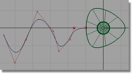
In this section, you will create part of the cable that connects the joystick to the computer.
Opening the tutorial file (optional)
If you successfully completed Part 3, you can proceed directly to the next step, Create the cable path curve.

If you were not successful in part 3, open the file called joystick_part4.wire, located in the wire directory of the CourseWare project. This file contains the completed model from Part 3.
 Watch Part
4 of the tutorial.
Watch Part
4 of the tutorial.
 or F5 to maximize
the Top view.
or F5 to maximize
the Top view.
You will create the cable on the left of the joystick, so you will modify the view to give you more space.
 and
and  (Windows) or and
  (Mac) keys down and use
the
(Mac) keys down and use
the  to zoom out of the view.
With the and (Windows) or and (Mac) keys still held down,
use the
to zoom out of the view.
With the and (Windows) or and (Mac) keys still held down,
use the  to pan the view, so there
is some free space to the left of the joystick.
to pan the view, so there
is some free space to the left of the joystick.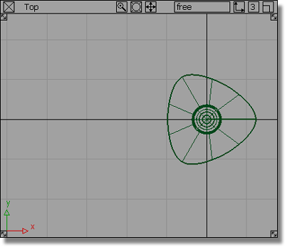
 .
(Windows) or (Mac) key down to turn grid
snapping on, and click on the grid intersection at the left side
of the base.
.
(Windows) or (Mac) key down to turn grid
snapping on, and click on the grid intersection at the left side
of the base.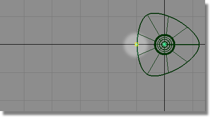
The first CV of the curve is created.
to position the second CV
to the left of the first. 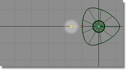
Release the mouse button. The second CV is placed horizontally away from the first.
Create the cable profile curve
Next, you will create a small circle for the cross-section profile of the cable.
 or F7 to maximize
the Back view.
or F7 to maximize
the Back view.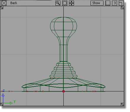
 .
.

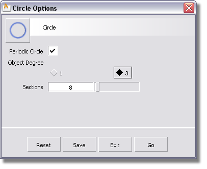
The current options have 9 sections which was set previously for the triangular shape. The default number of sections is 8 which creates a good general purpose circular shape.
Click the Reset button at the bottom of the Circle Options box to reset the options to the default values. Press Go to create the circle.
(Windows) or (Mac) key to turn grid snapping
on. Click near the origin in the Back window to place the circle
at the center of the base.
A small circle is placed at the origin. The CVs are highlighted in yellow and the manipulator is showing, but it won’t be used.
 or F6 to switch
to the Left view.
or F6 to switch
to the Left view. 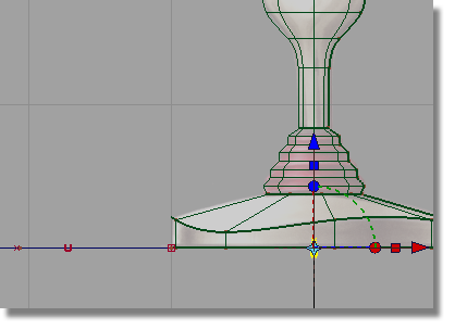
The circle is at the origin. Next, you will move the circle to the left edge of the joystick base, where the path curve begins.
(Windows) or (Mac) key to turn on grid
snapping. Click near the grid point where the path curve starts,
being careful not to select any other geometry.
The circle moves to the start of the path.
 to deselect the circle.
The circle and the start of the path curve need to move upwards, so the cable emerges from the middle of the base side wall.
 and drag a box around the
circle CVs and the first two CVs on the path curve.
and drag a box around the
circle CVs and the first two CVs on the path curve.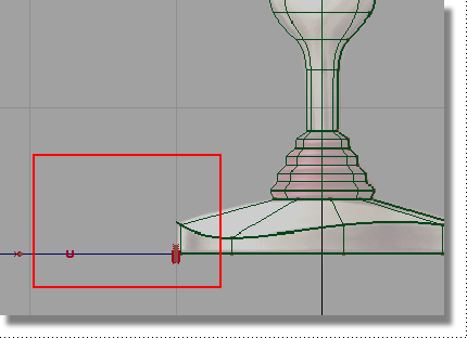
to move the selected CVs
upwards, so the circle sits in the middle of the sidewall of the
base.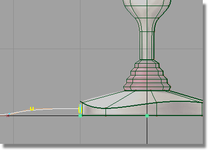
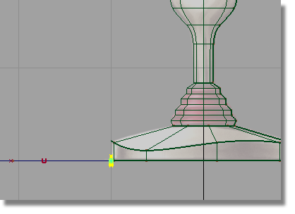
to deselect the CVs.
 or the F8 hotkey
to switch to the perspective view.
or the F8 hotkey
to switch to the perspective view.
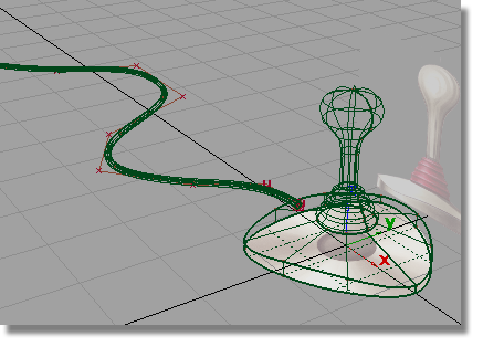
The small circle is at the start of the path curve, centered on the side wall of the base.
Next, you will create the extruded surface for the cable.
and (Windows) or and (Mac) keys and use the  to tumble the view, and
the to zoom in.
to tumble the view, and
the to zoom in.
To create the cable surface, you will extrude the small circle along the path curve.
 tool.
tool.
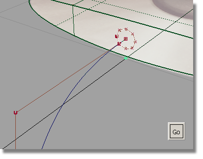
Select the Go button to choose the circle as the generation curve.
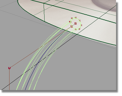
The extruded surface is created.
to deselect the surface.
 to save the current scene.


