Command entry:Particle View
Click Shape Mark in an event or add a Shape Mark operator to the particle system and then select it.
Use the Shape Mark operator to replace each particle with either a rectangle or a box cut out from the particle geometry with
an image mapped onto it. The image can be animated and the animation can be synchronized with particle events.
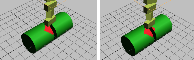
A typical application of Shape Mark would be to leave marks after particles impact objects in the scene. For example, when
a torpedo hits a boat and explodes, you could use Shape Mark to leave scorch marks on the boat surface.
TipBy default, the mark left by Shape Mark is always rectangular, no matter what shape the particles are. To leave a differently
shaped mark, choose the Shape group
Rectangle option, and use a
material in the same event with transparent areas to define the mark's outline. For example, apply a Mask map to the material's Opacity
channel, and to the map's Mask channel, apply a bitmap containing an alpha channel. On the Bitmap Parameters rollout, set
Mono Channel Output to Alpha.
NoteWith its default settings, the Shape Mark operator can generate coplanar faces, which the mental ray renderer cannot render
well. If you want to use mental ray rendering with Shape Mark, adjust the operator's settings as follows:
- In the Shape group, choose Box Intersection.
- Set Surface Offset to 0.01.
- Set Offset Variation to 0.005.
- Set Vertex Jitter to 0.002.
With these settings, faces are no longer coplanar, and the mental ray renderer gives better results.
Procedures
Example: To use Shape Mark:
- Determine which object is to receive the marks; this will be the contact object. Apply a deflector to this object.
- Set up your particle system with an event that causes particles to collide with the contact object deflector.
- At the end of this event, add a Collision test.
- In the Collision test, designate the deflector from step 1.
- Create a new event with the Shape Mark operator, and wire the Collision test to this event.
- In the Shape Mark operator Contact Object group, designate the object from step 1. Change the other Shape Mark settings as necessary.
Now, when the particles strike the contact object, they disappear, leaving marks on the object.
If you want the particles to bounce after leaving marks, rather than disappearing, use a Collision Spawn test instead, and turn off its Delete Parent check box. The spawned particles become the marks, and the original particles remain
in the first event.
- Optionally, add a Material operator to define the surface characteristics of the marks.
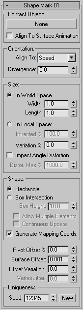
Interface
Contact Object group
Use this control for defining the object on which marks are to be left.
- [button]
-
Click this button, and then select an object in the scene to use as the contact object. The mouse cursor changes to a cross
shape when positioned over a valid object.
After picking a contact object, its name appears on the button.
- Align to Surface Animation
-
When on, Shape Mark takes into account surface changes due to vertex animation of the contact object. If Shape is set to Rectangle, then the mark changes its orientation and position to appear be stuck to the surface of the contact
object. If Shape is set to Box Intersection, then the mark changes shape along with that of the contact object. When off,
only transformation of the contact object is taken into consideration. Default=off.
Turn this on only if there is significant vertex animation at the contact point, such as with an animated water surface.
WarningThis option requires significant CPU and memory resources.
Orientation group
- Align To
-
Depending on the setting for Shape, Shape Mark creates either a rectangle or a box cutout on the contact geometry. The Orientation setting specifies how the
shape is oriented. In the mark's local coordinate system, the X axis is Length, the Y axis is Width, and with the box cutout,
Z is height. The Z axis is perpendicular to the surface of the object at the contact point.
The alignment choices are as follows:
- The Length direction is parallel to the projection of the particles' speed vector onto the contact plane.
- The Length direction is parallel to the projection of the particle's local coordinate axis X, Y, or Z, respectively, as the
particle moves toward the contact object.
- Uses a random Length direction in the contact plane.
- Divergence
-
Applies a range of random variation, in degrees, to the orientation of the Length direction. Unavailable when using the Random
option.
Size group
Use these settings to specify the coordinate system for setting the size of the mark, as well as the size parameters. The
numeric settings in this group are not animatable.
- In World Space
-
Sets the absolute size of the mark in system units, using the World coordinate system.
- Width/Length
-
With the In World Space option, sets the particle dimensions in system units. Range=0 to 1000000000. Default=1.0.
- In Local Space
-
Sets the mark size relative to the existing particle size, in local space. Particle Flow uses the dimensions of the existing
shape to determine the size of the “facing rectangle.”
- Inherited %
-
Sets the percentage of the mark size, relative to the existing particle size. Range=0 to 100. Default=100.0.
- Variation %
-
Sets the percentage by which particle size can vary. Default=0.0.
- Impact Angle Distortion
-
When on, increases the Length value of the mark according to the particle's angle of approach. This effectively stretches
the mark shape if particle approaches the contact geometry at a low angle. Available only when Align To is set to Speed. Default=off.
For example, if a drop of paint hits a surface perpendicularly, it creates a circular mark, but if it hits the surface at
a lower angle, the resulting shape is an ellipse.
- Distor(tion) Max %
-
Sets the maximum percentage by which Particle Flow may stretch the mark. Available only when Impact Angle Distortion is on.
Default=1000.
With very low angles of approach, the stretching factor can become very high. For example, value 500% means that the stretching
factor cannot exceed 5.
Shape group
These settings let you specify the mark-making object as a rectangle or a box. Default=Rectangle.
- Rectangle
-
The mark shape is a two-faced rectangle.
When using a material with Shape Mark, always choose this option.
- Box Intersection
-
With this option, Particle Flow creates a box for each particle that leaves a mark, and derives the mark shape from a Boolean
intersection between the contact object and the box.
- Box Height
-
Sets the height of the box used with the Box Intersection method. Available only with Box Intersection. Default=10.0.
- Allow Multiple Elements
-
When on, particles can leave marks on all parts of contact objects that contain multiple elements. When off, a particle marks
only the first element it collides with. Available only with Box Intersection. Default=off.
- Continuous Update
-
When on, the shape of the mark is recalculated at each frame, according to the current positions of the particle and the contact
surface. This option can consume a great deal of CPU time. Available only with Box Intersection.
- Generate Mapping Coords.
-
Allows correct application of the shape mark when using a mapped material. Default=on.
If you're not using a mapped material, you can save memory by turning this off.
_____
- Pivot Offset %
-
Shifts the position of the shape mark along its length dimension with respect to the pivot of the impacting particle. Default=0.0.
Range=-50.0 to 50.0.
By default, the center of the mark's length dimension coincides with the point where the particle's pivot strikes the contact
object. This setting lets you offset the mark's position to anywhere along its length.
NoteThe width dimension and the Box Intersection's height dimension are always centered at the intersection of the particle pivot
and the contact object's surface.
- Surface Offset
-
Specifies the distance of the shape mark above the contact object's surface. Default=0.001.
The mark is slightly elevated above the contact geometry to achieve the visual effect of the mark spot overlapping the contact
geometry. This parameter is not animatable.
- Offset Variation
-
Specifies the maximum extent of a random variation in the actual surface offset among particles. Default=0.0.
Adjusting this value can help to alleviate rendering artifacts with overlapping marks.
- Vertex Jitter
-
Specifies the maximum extent of a random variation in the positions of vertices of marks created using the Box Intersection
method. Available only with the Box Intersection method. Default=0.0.
Adjusting this value can help to alleviate rendering artifacts with overlapping marks.
Uniqueness group
The Uniqueness setting enables changing the randomization of the size/width variation.
- Seed
-
Specifies a randomization value.
- New
-
Calculates a new seed using a randomization formula.