Most of the camera controls are common to both kinds of cameras. This topic describes those controls.
To view a wider area, do either of the following:
To view a narrower area, do either of the following:
In a camera viewport, the FOV button lets you adjust the field of view interactively.
The camera viewport Perspective button also changes the FOV in conjunction with dollying the camera.
To match a camera to a film or video format:
 Render Setup dialog, in the Output Size group Output Size group, choose the type of output you want. Use either of the following methods.
To maintain the same lens, avoid using the FOV or Perspective controls among the navigation icon buttons.
To find a lens's focal length:
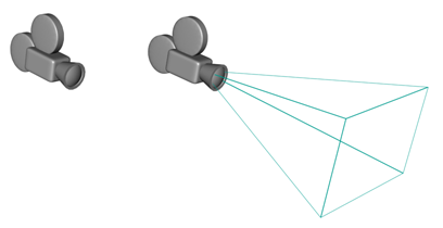
The camera's field-of-view cone appears outlined in light blue.
To display a camera's horizon line:
A dark gray line appears at the level of the horizon in the camera's viewport.
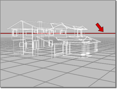
The horizon line shown in the viewport.
The horizon line might not be visible if the horizon is beyond the camera's field of view, or if the camera is tilted very high or low.
To change the environment range:
By default, the Near Range=0.0 and the Far Range equals the Far clipping plane value.
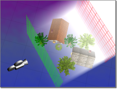
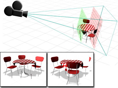
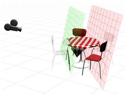
Environment ranges determine the near and far range limits for atmospheric effects you set in the Environment dialog.
To see the environment ranges in viewports:
The environment range displays as two planes. The plane closest to the camera is the near range and the one farthest from the camera is the far range.
When Clip Manually is off, the camera ignores the location of the Near and Far clipping planes, and their controls are unavailable. The camera renders all geometry within its field of view.
Objects closer to the camera than the Near distance are not visible to the camera and aren't rendered.
Objects farther from the camera than the Far distance are not visible to the camera and aren't rendered.
You can set the Near clipping plane close to the camera so that it doesn't exclude any geometry, and still use the Far plane to exclude objects. Similarly, you can set the Far clipping plane far enough from the camera that it doesn't exclude any geometry, and still use the Near plane to exclude objects.
The Near value is constrained to be less than the Far value.
If the clipping plane intersects an object, it cuts through that object, creating a cutaway view.
The effect of clipping planes
To apply a multi-pass rendering effect to a scene:
Depth Of Field is the only multi-pass effect that is provided with 3ds Max by default.
The Preview button has no effect if a camera viewport isn't active.
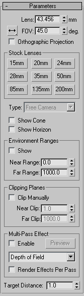
Sets the camera's focal length in millimeters. Use the Lens spinner to give the focal length a value other than the preset "stock" values on the buttons in the Stock Lenses group box.
Changing the Aperture Width value on the Render Setup dialog also changes the value in the Lens spinner field. This doesn't change the view through the camera, but it does change the relationship between the Lens value and the FOV value, as well as the aspect ratio of the camera's cone.
Determines how wide an area the camera views (field of view). When FOV Direction is horizontal (the default), the FOV parameter directly sets the arc of the camera's horizon, measured in degrees. You can also set the FOV Direction to measure FOV vertically or diagonally.
You can also adjust the field of view interactively in a camera viewport by using the FOV button.
When on, the camera view looks just like a User view. When off, the camera view is the standard perspective-like view. While Orthographic Projection is in effect, the viewport navigation buttons behave as they ordinarily do, except for Perspective. Perspective function still moves the camera and changes the FOV, but the Orthographic Projection cancels the two out, so you don't see any change until you turn off Orthographic Projection.
Changes the camera's type from a Target camera to a Free camera, and vice versa.
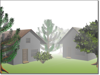
Determine the near and far range limits for the atmospheric effects set on the Environment panel. Objects between the two limits fade between the Far % and Near % values.
Sets options to define clipping planes. In viewports, clipping planes are displayed as red rectangles (with diagonals) within the camera's cone.
Sets near and far planes. Objects closer than the near clipping plane or farther than the far clipping plane are invisible to the camera. The limit of the Far Clip value is 10 to the power of 32.
With manual clipping on, the near clipping plane can be as close to the camera as 0.1 unit.
Conceptual image of Near and Far clipping planes.
These controls let you assign a depth-of-field or motion blur effect to the camera. When generated by a camera, these effects generate blurring by rendering the scene in multiple passes, with offsets. They increase rendering time.
Lets you choose which multi-pass effect to generate, Depth Of Field or Motion Blur. These effects are mutually exclusive. Default=Depth Of Field.
This list also lets you choose Depth of Field (mental ray), which lets you use the mental ray renderer's depth of field effect.
When on, applies rendering effects, if any are assigned, to each pass of the multi-pass effect (depth of field or motion blur). When off, applies rendering effects only after the passes that generate the multi-pass effect. Default=off.
Turning off Render Effects Per Pass can improve the render time for multi-pass effects.


 Create panel