Command entry:
Main toolbar


(Render Setup)
Render Setup dialog
Render Elements panel
Render Elements rollout
Command entry:Rendering menu
Render Setup
Render Setup dialog
Render Elements panel
Render Elements rollout
This topic describes the available types of render elements and how to use them.
These are the elements you can choose to render separately:
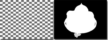
- Alpha: A grayscale representation of the alpha channel, or transparency, of the scene. Opaque pixels appear in white (value=255)
and transparent in black (value=0). Translucent pixels appear in gray. The darker the pixel, the more transparent it is.
The alpha channel can be useful when you composite elements.
- Atmosphere: The atmospheric effects in the rendering.
- Background: The background of the scene.
Other elements do not include the scene background. Include this element if you want to use the background in compositing.
The background is not trimmed against geometry, so elements should be composited over the background. See Compositing Rendered Elements.
- Blend: A custom combination of the previous elements.
The Blend element displays an additional Blend Element Parameters rollout.
- Diffuse: The diffuse component of the rendering.
The Diffuse element displays an additional Diffuse Texture Element rollout.
- Hair And Fur: The component of the rendering created by the Hair And Fur Modifier (World Space). See Hair And Fur Render Element.
- Illuminance HDR Data: Generates an image containing 32–bit floating-point data that can be used for analyzing the amount of light that falls on
a surface perpendicular to its normal. See Illuminance HDR Data Element Parameters Rollout.
- Ink: The Ink component (borders) of Ink 'n Paint materials.
- Lighting: The effect of direct and indirect lights and shadows in the scene.
The Lighting element displays an additional Lighting Texture Element rollout.
- Luminance HDR Data: Generates an image containing 32–bit floating-point data that can be used for analyzing the perceived brightness of a surface
after light has been “absorbed” by the material of the surface. See Luminance HDR Data Element Parameters Rollout.
- Material ID: Renders the material ID information assigned to an object. This information is useful when you are making selections in other
image-processing or special-effects applications, such as Autodesk Combustion. For example, you could select all of the objects
with a given material ID in Combustion. The material ID corresponds to the value you set for the material with the material
ID channel. Any given material ID will always be represented by the same color. The correlation between a specific material
ID and a specific color is the same in Combustion. See Material ID Channel Flyout .
- Matte: Renders a matte mask, based on selected objects, material ID channel (effects IDs), or G-Buffer IDs.
The Matte element displays an additional Matte Texture Element rollout.
- mr A&D: These elements render various components of the Arch & Design material to HDR compositors such as Autodesk Toxik. For details,
see mr A&D Elements.
- mr Labeled Element: Renders a branch of a map tree that you specify using a label. For details, see mr Labeled Element Parameters Rollout
- mr Shader Element: Outputs the raw contribution of any mental ray shader in the scene. This includes standard 3ds Max materials and maps that are converted to mental ray shaders in the translation process. For details, see mr Shader Element Parameters Rollout
- Object ID: Renders the object ID information assigned to the object. See Object ID Element Rollout.
- Paint: The Paint component (surfaces) of Ink 'n Paint materials.
- Reflection: The reflections in the rendering.
- Refraction: The refractions in the rendering.
- Self-Illumination: The self-illumination component of the rendering.
- Shadow: The shadows in the rendering. This element saves black-and-white shadows only. See Compositing Rendered Elements.
- Specular: The specular component of the rendering.
- Velocity: The motion information which can be used in other applications for things such as creating motion blur or retiming an animation.
The Velocity element displays an additional Velocity Element Parameters rollout.
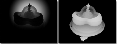
- Z Depth: A grayscale representation of the Z depth, or depth within the view, of objects within the scene. The nearest objects appear
in white, and the depth of the scene in black. Intermediate objects are in gray, the darker the deeper the object is, within
the view.
The Z Depth element displays an additional Z Element Parameters rollout.
When you render one or more elements, a normal complete rendering is also generated. In fact, the element renderings are generated
during the same rendering pass, so rendering elements costs little extra render time.
Rendering to elements is available only when you do production rendering with the default scanline renderer or the mental ray renderer.
NoteThe default scanline renderer supports a maximum of 32 render elements per scene. The mental ray renderer does not limit the
number of render elements. If you're using a third-party renderer, check the product documentation for a possible limit on
the number of render elements.
NoteWhen using the default scanline renderer,
Antialiasing must be on in order to render elements. With Antialiasing off, rendering elements is disabled.
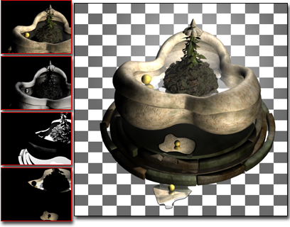
Example
Here is a rendering of a fountain, against a checkered background, and various elements.
Compositing Rendered Elements
In general, you can composite elements using additive composition, which is independent of the compositing order.
The main exceptions are the background element, atmospheres, and shadows.
- Background: The background is not trimmed against geometry, the background should be composited under the other elements.
- Atmosphere: The atmosphere element should be composited over all other elements.
- Black-and-white shadows: Black-and-white shadows should be composited over the rest of the image (aside from the atmosphere), to dim color in the shadowed
areas. This technique does not take colored lighting into account.
In other words, the layers when you composite using black-and-white shadows appear like this:
Top: Atmosphere
Second from top: Shadow element
Middle: Diffuse + Specular + ... (other elements)
Bottom: Background
"Screen" Compositing for Specular and Reflection Elements
The other exception to additive composition is when specular or reflection elements have been generated by certain material
shaders. These shaders generate specular and reflection elements you must composite differently:
- Anisotropic
- Multi-Layer
- Oren-Nayar-Blinn
Shaders are assigned on a per-material basis, in the Material Editor. If you render specular or reflection elements in a scene
that uses these shaders, then composite them with the diffuse and other foreground components (aside from colored shadows,
as described above), by overlaying them using an operation called "Screen" in some compositing programs.
Screen compositing uses this formula to combine elements:
Background * (1 - Foreground) + Foreground
The background is multiplied by the inverse of the foreground color, and then the foreground color is added to the result.
For more information, see the documentation for the compositing program you use.
Procedures
To have the Render Elements dialog assign names to the rendered element files automatically:
- Assign an output file name and file type for the (entire) rendered scene using the Files buttonFiles on the Common Parameters rollout of the Render Setup dialog.
- On the Render Elements rollout, use the Add button to specify elements for rendering (see following procedure).
To render elements to files without rendering the entire scene to a file, follow this procedure, and then turn off Common
panel Common Parameters rollout Render Output group Save File.
To add an element for rendering:
- Click Add.
- On the Render Elements dialog, do one of the following:
- Highlight the name of an element, and then click OK.
- Double-click the name of an element.
If you have assigned a file name for the entire rendering, the new element is assigned a file name automatically. Otherwise,
use the Files button in the Selected Element Parameters group to assign an output file name and file type for the element
rendering.
- If the element is one (such as Blend or Z Buffer) that has additional parameters, adjust these parameters in the appropriate
rollout.
To render the separate elements:
- Add the elements you want to render.
TipYou can use the Enable button (in the Selected Element Parameters rollout) to disable individual elements for a particular
rendering pass.
- If you haven't assigned file names automatically (see the first procedure, preceding), use the Browse [...] button in the
Selected Element Parameters group to assign an output file name and file type for the element rendering.
- Make sure Elements Active (at the top of the Render Elements rollout) is turned on, and then click Render to render the scene.
The rendered elements are also displayed on the desktop, each in its own window. (The windows cascade on top of each other.)
To generate a Combustion™ workspace (CWS) file that contains the rendered elements:
- In the Output to Combustion group, turn on Enable.
If you have assigned a file name for the entire rendering, the new element is assigned a file name automatically. Otherwise,
use the Files button in the Output to Combustion group to assign an output file name for the CWS file.
- If you want to change the file or pathname click ... [ellipsis].
- Do one of the following:
Interface
- Add
-
- Merge
-
Click to merge the render elements from another 3ds Max scene. Merge displays a file dialog so you can select the scene file to get the elements from. The list of render elements
in the selected file is added to the current list.
- Delete
-
Click to delete the selected elements from the list.
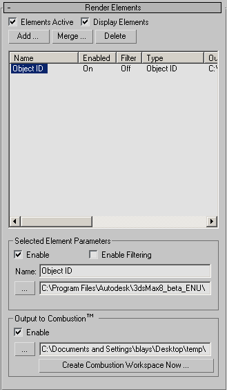
- Elements Active
-
When on, clicking Render renders the separate elements. Default=on.
- Display Elements
-
When on, each rendered element is displayed in its own window, which is a feature-reduced version of the Rendered Frame Window. When off, the elements are rendered to files only. Default=on.
The windows for each rendered element open cascaded on top of each other. Move one element's window to see another's.
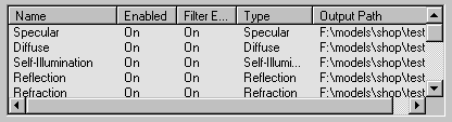
Element Rendering list
This scrollable list shows the elements to render separately, and their status. To resize the columns in the list, drag the
border between two columns.
The list includes the following columns:
- Name
-
Shows the name o f the element. You can change the default name of elements, in the Selected Element Parameters group.
To select an element, click its name in the list. Use Ctrl+click to select additional elements, or Shift+click to select a contiguous group of additional elements.
- Enabled
-
Shows whether the element is enabled.
- Filter
-
Shows whether the active antialiasing filter is enabled for the element.
- Type
-
Shows what type of element this is.
This field is useful if you have changed the name of an element.
- Output Path
-
Shows the path and file name for the element.
Selected Element Parameters group
These controls are for editing selected elements in the list.
- Enable
-
Turn on to enable rendering the selected elements. Turn off to disable rendering. Default=on.
The Enabled column of the elements list shows whether or not an element is enabled.
- Enable Filtering
-
When on, applies the active antialiasing filter to the rendered element. When off, the rendered element does not use the antialiasing filter. Default=on.
The Filter column of the elements list shows whether or not the filter is enabled for an element.
Disabling antialiasing can improve rendering time, although the rendered element that results might appear jagged.
NoteTurning off Enable Filter disables only general antialiasing and map filtering. Edge blending still occurs when this switch
is off.
- Name
-
Shows the name of the currently selected element. You can type in a custom name for the element.
This control is unavailable when multiple elements are selected.
- [...] (Browse)
-
The text box lets you enter a path and file name for the element. Alternatively, click the [...] ( ellipsis) button to open
the Render Element Output File dialog, which lets you choose a folder, file name, and file type for the element.
This control is available only when a single element is highlighted.
NoteIf you first assign a file name and path for the complete rendering on the Render Setup dialog
Common Parameters rollout, the render elements feature uses this name and path automatically as the basis for names of the various elements. It appends
an underscore (_) and then the name of the element to the basic file name.
For example, if the render file name is "C:\render\image.jpg", when you add a Specular render element, the default path and file name for the rendered specular element is "C:\render\image_specular.jpg".
Similarly, when you enable output to a Combustion workspace (CWS) file, the file name you assigned is the default name of the CWS file.
For example, if the render file name is "C:\image.jpg", when you enable Combustion output, the default path and file name is "C:\image.cws".
Output to Combustion group
When on, generates a Combustion Workspace (CWS) file that contains the elements you are rendering. You can use this file in the Combustion software, and you can use Combustion
workspaces in the Combustion map.
WarningIf you are rendering elements to composite over a background, make sure that the file format for the Diffuse, Shadows, and
Alpha elements supports an alpha channel. The formats we recommend for this purpose are:
RLA,
RPF,
PNG, or
TGA.
Warning 3ds Max supports some file types that Combustion does not. For use with Combustion, do not render elements as EPS files. If you render
to this format, the CWS file is not saved. See your Combustion documentation for more information on supported file formats.
- Enable
-
When on, creates a CWS file that contains the elements you have rendered.
- [...] (Browse)
-
The text box lets you enter a path and file name for the CWS file. Alternatively, click the [...] (ellipsis) button to open
the Save To Combustion dialog, which lets you choose a folder and file name for the CWS file.
- Create Combustion Workspace Now
-
When clicked, creates a Combustion workspace (CWS file). This button makes it possible to create a Combustion workspace without
rendering.
NoteYou must add at least one render element for this file to be created and the Render Output type on the Common panel must be
set to AVI, RPF, CIN, JPG, PNG, MOV, RGB, RLA, TGA, TIF, or EXR.