The Edit panel provides a variety of tools for modifying polygon-based objects, including transform constraints, edge and loop creation, and editing texture coordinates.
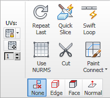
Edit panel on minimized ribbon
Edit panel at Object level

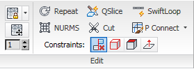
Edit panel at sub-object levels
 Preserve UVs
When on, you can edit sub-objects without affecting the object's UV mapping. You can choose any of an object's mapping channels to preserve or not; see Preserve UVs Settings, following. Default=off.
Without Preserve UVs, there is always a direct correspondence between an object's geometry and its UV mapping. For example, if you map an object and then move vertices, the texture moves along with the sub-objects, whether you want it to or not. If you turn on Preserve UVs, you can perform minor editing tasks without changing the mapping.
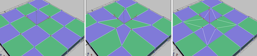
Original object with texture map (left); Scaled vertices with Preserve UVs off (center); Scaled vertices with Preserve UVs on (right)
Opens the Preserve Map Channels dialog, which lets you specify which vertex color channels and/or texture channels (map channels) to preserve. By default, all vertex color channels are off (not preserved), and all texture channels are on (preserved).
 Tweak (UVs)
When on, you can adjust the UVW mapping on your model directly in the viewport using a paintbrush-like tool by dragging over the vertices of the model to pull the texture vertices around. When active, the UV Tweak Options panel opens on the ribbon. You can use these settings to adjust the brush strength and other parameters.
By tweaking UVs with this tool you can quickly adjust areas of stretching in the UVW mapping without the need to add any modifiers. Use the spinner to choose the desired mapping channel and then start the tool. When finished tweaking, right-click to exit the tool.
To revert to untweaked UVs, paint with the Alt key held down. Other keyboard alternatives are covered in the UV Tweak Options topic.

Drag a vertex to adjust the UVs
When working with Tweak, it’s useful to have a material applied to the model that enables you to easily spot stretching in the mapping. A checker map is suitable for this purpose.
 Repeat Last
Repeats the most recently used command.
For example, if you extrude a polygon, and want to apply the same extrusion to several others, select the others, and then click Repeat Last.
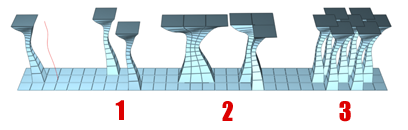
You can apply a spline extrusion of a single polygon (left) repeatedly to other single polygons (1) or to multiple polygon selections, contiguous (2) or not (3).
 QuickSlice
Lets you quickly slice the object without having to manipulate a gizmo. Make a selection, click QuickSlice, and then click once at the slice start point and again at its endpoint. You can continue slicing the selection while the command is active.
To stop slicing, right-click in the viewport, or click QuickSlice again to turn it off.
With Quickslice on, you can draw a line across your mesh in any viewport, including Perspective and Camera views. The mesh is sliced interactively as you move the line endpoint.
 SwiftLoop
Place edge loops by clicking. Turn on, then click anywhere to insert an edge loop automatically, perpendicular to the edge closest to where you click. Continue clicking edges or right-click to exit.
Additional features include the ability to slide edges or edge loops in different ways. Following are the different functions of the tool, which depend on which keyboard keys are pressed:
 Use NURMS
Applies smoothing via the NURMS method and opens the Use NURMS Panel. As implemented in Edit/Editable Poly, NURMS is an easy-to-use, procedural mesh-smoothing method that gives you overall control over smoothing parameters.
You control the degree of smoothing with the main Iteration setting, and, optionally the Iteration setting in the Render group as well.
 Cut
Cut
Lets you create edges from one polygon to another or within polygons. Click at the start point, move the mouse and click again, and continue moving and clicking to create new connected edges. Right-click once to exit the current cut, whereupon you can start a new one, or right-click again to exit Cut mode.
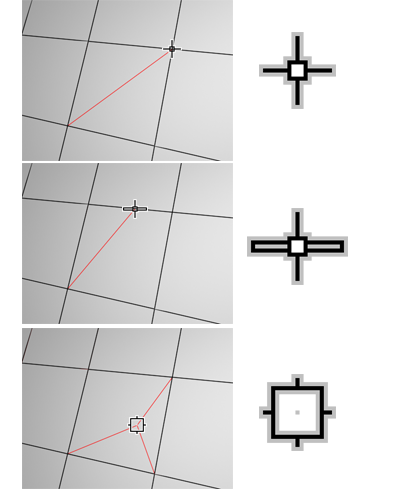
While cutting, the mouse cursor icon changes to show the type of sub-object it’s over, to which the cut will be made when you click. The following illustration shows the three different cursor icons.
 Paint Connect
When on, you can paint connections interactively between edges and vertices.
Paint Connect offers a variety of operational modes, depending on which key or keys are pressed:
 Constraints
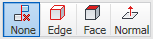
Lets you use existing geometry to constrain sub-object transformation. Choose the constraint type:
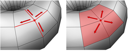
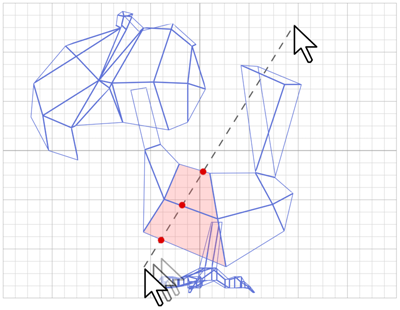
When set to Edge, moving a vertex will slide it along one of the existing edges, depending on the direction of the transformation. If set to Face, the vertex moves only on the polygon’s surface.
The Use NURMS panel opens when the Use NURMS button on the modeling ribbon Edit panel is active, and provides access to all controls for how NURMS smoothes object surfaces.
The Tweak feature lets you adjust texture coordinates directly on the geometry by “painting”; that is, dragging with a circular brush. These settings let you modify the brush parameters.