Command entry:
Create panel


(Space Warps)
Geometric/Deformable
Object Type rollout
Conform
Command entry:Create menu
Space Warps
Geometric/Deformable
Conform
The Conform space warp modifies its bound object by pushing its vertices in the direction indicated by the space warp icon,
until they hit a specified target object, or until the vertices move a specified distance from their original position.
After creating a Conform space warp, you specify a target object in the Conform parameters, and then bind the Conform to the
object you want to deform. You rotate the Conform icon to specify the travel direction (toward the target object). The vertices
of the deformed object move until they hit the target object.
There is also a Conform compound object that provides additional methods of conforming one object to another.
Procedures
Example: Using the Conform space warp:
Begin by making two objects.
- Create a terrain by making a wide, flat box with plenty of Length and Width segments (or a quad patch). Apply a Noise modifier
and adjust its parameters to result in a bumpy terrain (not mountainous, but low and irregular).
- Create a short, wide cylinder whose radius is about one-eighth the area of the box (like a coin). You'll animate the cylinder
to float diagonally over the surface of the terrain.
- Set Cap Segments in the cylinder to 4, and position the cylinder to float over the terrain.
- Set the object color of the cylinder to contrast with the color of the terrain.
- Move the cylinder inside one corner of the terrain as seen from the Top viewport. Turn on Animate, move to frame 100, and
move the cylinder to the opposite corner of the terrain.
The coin/disk moves from one corner of the terrain to the other.
The terrain will become the target object, and the cylinder the deformed object. The next step is to create the Conform space
warp and bind it to the cylinder.
- On the Create panel, choose Space Warps, and then, from the drop-down list, choose Geometric/Deformable. Click the Conform
button.
- In the Top viewport, in the center of the terrain, drag outward to create the Conform space warp.
- Click the Pick Object button, and then click the terrain box.
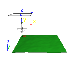
- In the Front viewport, drag the space warp up until it's above the cylinder.
As seen in the Front viewport, the terrain is at the bottom, the cylinder is between the terrain and the space warp, and the
space warp is at the top.
- Bind the space warp to the cylinder.
The cylinder becomes a disk that seems to be painted on the surface of the terrain.
- Drag the time slider to see the cylinder/disk move across the box, following the terrain.
Because the vertices are pushed almost to the level of the terrain, the faces of the two object might intersect. In the following
steps, you'll fix this by adjusting the standoff distance between the target surface and the pushed vertices. Then you'll
go on to affect only selected vertices in the cylinder.
- Select the Conform space warp, and open the Modify panel.
- Set Standoff Distance to 3.
You can now clearly see the surface of the disk above the terrain.
- Set the Standoff Distance to 20.
The disk floats 20 units above the terrain. Next, change the affected vertices.
- Select the disk/cylinder.
- In the modifier stack display, click the Cylinder item so it's highlighted in gray.
- Apply a Mesh Select modifier.
- At the Vertex sub-object level, in the Front viewport, region-select the bottom cap vertices of the cylinder.
- Remain at the sub-object level, and in the stack display click the Conform Binding item.
- In the viewport, select the Conform icon.
- In the Modify panel, turn on Use Selected Vertices.
Now that only the bottom cap vertices are selected, the rest of the cylinder is restored. If you adjust the viewing angle
and play the animation, you'll see that the bottom face of the cylinder follows the terrain, while the rest of the cylinder
retains its shape.
Interface
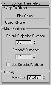
Wrap To Object group
These options provide controls to select the target object.
- Pick Object
-
Click this, and then select an object in the scene. The object you select becomes the barrier against which the bound object's
vertices will be pushed.
- Object
-
Displays the name of the picked object.
Move Vertices group
These options affect how the vertices are moved.
- Default Projection Distance
-
The distance a vertex in the bound object moves from its original location if it does not intersect the target object.
- Standoff Distance
-
The distance maintained between the vertex and the surface of the target object. For example, if set to 5, the vertices can
be pushed no closer than 5 units from the surface of the target object.
- Use Selected Vertices
-
When on, only the sub-object selection of vertices on the Stack are pushed. When off, all vertices in the object are pushed
regardless of the Stack selection.
Display group
- Icon Size
-
Specifies the size of the icon.