 Command entry:Click or right-click the General viewport label (“[ + ]”) .
  General viewport label menu Configure Viewport Configuration dialog Rendering Method tab
For legacy viewport drivers (Direct3D, OpenGL, and so on), The Rendering Method panel of the Viewport Configuration dialog sets the rendering method for either the current viewport or all viewports.
To set the viewport rendering method:
Configure Viewport Configuration dialog Rendering Method tab.
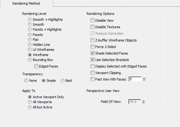
When you open this dialog, the settings reflect the current viewport settings.
Determines how 3ds Max displays objects.
Renders each polygon in its raw, unshaded diffuse color, disregarding any contribution from ambient lighting or light sources. This rendering method is useful when it's more important to see each polygon than to see its shading. It's also a good way to check the results of bitmaps created with Render to Texture.
A wireframe mode that hides faces and vertices with normals pointing away from the viewpoint, as well as any parts of objects that are obscured by closer objects. In this display mode
only, the wireframe color is determined by the Viewports Hidden Line Unselected color, not the object or material color. See Colors Panel.
Draws objects as bounding boxes with no shading applied. A bounding box is defined as the smallest box that completely encloses an object.
Edges are displayed using the object wireframe color, while surfaces use material colors (if a material is assigned). This lets you create contrasting colors between the shaded surfaces and the wireframe edges. You can switch these around with the Display Color rollout settings on the Display panel.
Applies the current settings to the active viewport only, to all viewports, or to all the viewports except the active one.
These check boxes modify either the shading modes or the wireframe modes. They refer to the viewport renderer only, not to the scanline renderer or any other renderer.
Disables the Apply To viewport selection. A disabled viewport behaves like any other viewport while active. However, when you change the scene in another viewport, the view in the disabled viewport does not change until you next activate it. Use this function to speed up screen redraws when you are working on complex geometry.
Select to turn off display of texture maps assigned to objects. Turn off to show the maps assigned to objects.
This option is enabled only when you are using the software display driver. When on, 3ds Max redraws the viewport using pixel interpolation (perspective-corrected). The redrawn image remains until you force the viewport to redraw for any reason. This option has an effect only when the viewport is shaded and at least one object's map is displayed.
Draws the wires ordered according to depth in the scene. Otherwise wires may be drawn out of order to speed the viewport display. This option is generally needed only when sub-object selections are "hidden" by lines drawn out of order. For example, you select the front edges of a box, but they don’t appear highlighted in red, because the white lines from the rear may get drawn last. Activate this only if you find that selections are obscured or if you need the viewport redrawn from back to front.
Set to render both sides of faces. See 2-Sided. Turn off to render only faces with normals toward the viewer. Usually, you'll want to keep this option off to speed redraw time. You might want to turn it on if you need to see the inside as well as the outside of objects, or if you've imported complex geometry in which the face normals are not properly unified.
Backface Cull switch.
Toggles the display of highlighted edges for selected objects when the viewport is in a shaded mode, such as Smooth, Smooth+Highlights, Facets+Highlights, or Facets. When on in these modes, the wireframe edges of selected objects appear along with the shaded surfaces. This is helpful when selecting multiple objects or small objects.
When on, interactively sets a near and far range for viewport display. Two arrows at the edge of the viewport allow you to determine where the clipping occurs. Tick marks correspond to the extents of the viewport, the lower tick is the near clipping plane, and the upper tick sets the far clipping plane. This does not affect the rendering to output, only the viewport display.


