Pelt mapping is useful for mapping organic models such as characters and creatures. This feature gives you a special editor with a virtual stretcher and springs that let you easily “pull” a complex UVW map flat. The result more closely approximates the actual shape of the object than other mapping methods, making it easier to create convincing texture maps.
The primary function of the Pelt Map dialog is to let you stretch out the UVW coordinates into a flat, unified map that you can then use for texturing. When the dialog is open, the stretcher appears in the Edit UVWs dialog window as a circle of points, each of which is attached to a vertex on a pelt seam. You can manipulate these vertices exactly as any other vertex in the editor, selecting, rotating, moving, and so on. Other special functions available on the dialog let you straighten out stretcher vertices, snap them to the pelt seams, and so on.
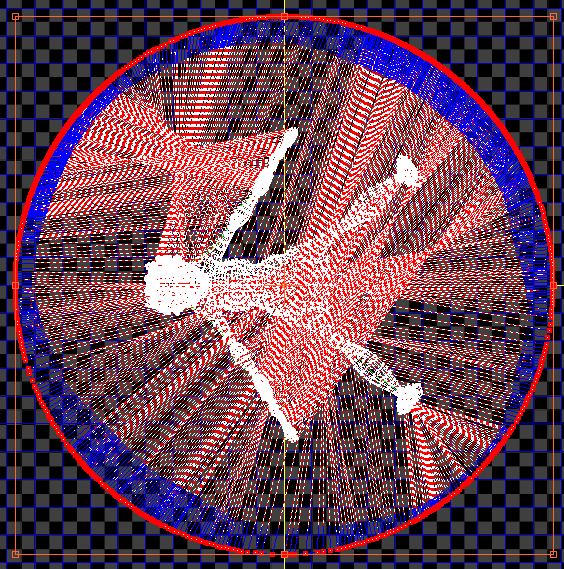
The stretcher points surround the pelt UVs in the Edit UVWs dialog window.
The lines connecting the stretcher vertices to the pelt-seam vertices function as springs that pull the pelt seams outward in an animated simulation. After you set up the pelt UVs and the stretcher shape, you run the simulation by clicking the Simulate Pelt Pulling button. Depending on the results, further adjustment and simulation might be required.
While Pelt mode is active and the Edit UVWs dialog is open, most standard UVWs editing functions are also available. So, for example, instead of stretching the entire pelt, you could select a subset of UVs to stretch. To access any commands that are unavailable in Pelt mode, such as Mapping menu commands, simply close the Pelt Map dialog.

 (Convert Edge Selection To Seams). This copies the edge selection to seams.
Alternatively, if you didn't select edges to convert to seams, use  (Edit Seams) and/or
  (Point-to-Point Seams) to specify seams in the viewports.
 (Expand Face Selection to Seams).
This expands the face selection to the full size of the region defined by the seam.
 (Pelt).
This opens the Pelt Map dialog. It also opens the Edit UVWs dialog, if necessary, and displays the pelt UVWs and the stretcher in the editor window. By default, the stretcher appears as a circle of points centered on the pelt UVWs, with only the stretcher vertices selected. Also, springs, represented as dashed lines, connect the stretcher points and the pelt-seam vertices.
The springs contract, pulling the pelt seam vertices toward the stretcher points. The internal UV vertices are also affected by this action. You can adjust the extent to which they're affected with the Decay setting on the Pelt Options rollout.
The primary Pelt Map commands are activated via the buttons on the Quick Pelt rollout. Other functions on this dialog let you adjust various stretching parameters.
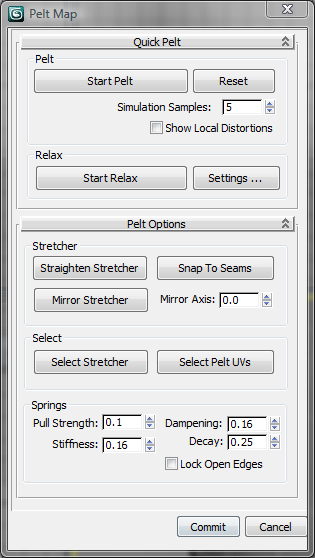
These are the main controls for the simulation, in which the springs attached to the stretcher pull the pelt seam vertices out, flattening the UVs. For best results, alternate between running the simulation (click Start Pelt) and relaxing the mesh.
Runs the simulation, pulling the pelt seam vertices towards the stretcher points. The simulation runs continuously until you stop it by pressing Esc or clicking Stop Pelt (the same button). You can also stop it by clicking Reset, or Commit or Cancel at the bottom of the dialog.
Pelt affects only selected texture vertices. However, if no texture vertices are selected, it affects all of them.
When on, depicts the differences between texture vertices and mesh vertices for visible faces; that is, faces selected in the viewport when Display Only Selected Faces is on. For more information, see Show Edge Distortion.
Normally, when showing edge distortion, 3ds Max takes the entire mesh into account. This can result in an unrealistic depiction of distortion when you use pelt mapping on only part of a mesh (for example, the head of a character). For a more accurate depiction of distorted edges with respect to the part of the mesh that you're currently pelt-mapping, turn on this option, turn on Filter Selected Faces, and select in the viewport only the faces that you're currently pelt-mapping.
Opens the Relax Tool dialog for setting relax parameters. While this dialog is open, you can start the relax by clicking its buttons or the Start Relax button on the Pelt Map dialog.
These tools help adjust the stretcher shape.
Lets you specify a polygonal outline for the stretcher by moving points. When this mode is active, move one stretcher vertex, and then move a second, non-adjacent point to line up all intervening vertices in a straight line between the two. This process is fully interactive; as you move the second vertex, the intervening vertices continually change position to maintain the straight line. Continue moving vertices to create a polygonal outline; to quit, click Straighten Stretcher again.
Lets you specify the orientation of the mirror axis. The axis takes the form of three yellow lines forming a T. The leg of the T indicates the side that will be mirrored when you use Mirror Stretcher (see preceding), and the crossbar indicates the axis across which the mirroring will occur. Default=0.0. Range=0.0 to 360.0.
These commands let you select all the stretcher points or the pelt UVs. As with other selection methods, you can press and hold Ctrl when you use either of these to add to the current selection. That is, to select all stretcher points and pelt UVs, click one button, press and hold Ctrl, and then click the other button.
These parameters control the springs that are used to stretch the pelt. In most cases you won’t need to change these values, except possibly for Pull Strength.
Locks the open edges in place. This typically applies to using the stretcher on a partial selection of mapping vertices in the pelt region. When Lock Open Edges is on, selected vertices next to unselected vertices tend to stay in place during stretching. When Lock Open Edges is off, the selected vertices tend to pull away from the unselected vertices.


