The panels described in this topic provide tools for subdividing meshes, changing triangulation, aligning objects and sub-objects, hiding and unhiding sub-objects, and setting properties such as smoothing. These panels are available only on the Graphite Modeling Tools tab of the modeling ribbon.
The panels covered in this topic are:
The Subdivision panel provides tools for increasing mesh resolution parametrically for smoothing, displacement, and tessellation. It is available at the object level and at all sub-object levels.

 MeshSmooth
Smoothes the object using the current settings. This command uses subdivision functionality similar to that of the MeshSmooth modifier with NURMS Subdivision, but unlike NURMS subdivision, it applies the smoothing instantly to the selected area of the control mesh.
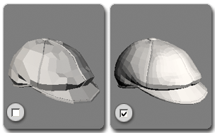
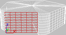
Smoothing a low-poly object with NURMS subdivision
Opens the MeshSmooth caddy, which lets you specify how smoothing is applied.
 Tessellate
Subdivides all polygons in the object based on the Tessellation settings.
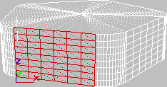
Tessellation is useful for increasing local mesh density while modeling. You can subdivide any selection of polygons. Two tessellation methods are available: Edge and Face.
Opens the Tessellate caddy, which lets you specify how smoothing is applied.
 Use Displacement
Opens the Displacement panel, with parameters for setting how to subdivide the mesh for displacement. For details, see Subdivision Displacement Rollout (Polymesh).
The Triangulation panel, also labeled “Tris” in some configurations, appears at all sub-object levels except Vertex, and provides tools for changing how polygons are subdivided into triangles for rendering purposes. The Retriangulate tool is available only at the Polygon and Element levels.

 Edit
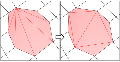
EditLets you modify how polygons are subdivided into triangles by drawing internal edges, or diagonals.
In Edit Triangulation mode, you can see the current triangulation in the viewport, and change it by clicking two vertices on the same polygon.
To edit triangulation manually, turn on this button. The hidden edges appear. Click a polygon vertex. A rubber-band line appears, attached to the cursor. Click a non-adjacent vertex to create a new triangulation for the polygon.
 Turn
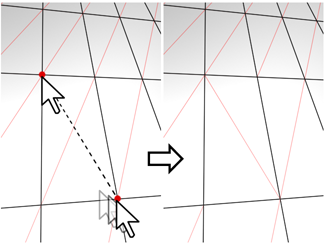
TurnLets you modify how polygons are subdivided into triangles by clicking diagonals. When you activate Turn, the diagonals become visible as dashed lines in wireframe and edged-faces views. In Turn mode, click a diagonal to change its position. To exit Turn mode, right-click in the viewport or click the Turn button again.
Each diagonal has only two available positions at any given time, so clicking a diagonal twice in succession simply returns it to its original position. But changing the position of a nearby diagonal can make a different alternate position available to a diagonal.
For more information on how to use Turn with the enhanced Cut tool, see this procedure.
 Retriangulate
The Align panel provides tools for aligning objects and sub-object selections with the view or grid, or simply flattening a mesh. It is available at the object level and at all sub-object levels.

 Make Planar
 To View
Aligns all vertices in the object to the plane of the active viewport. At sub-object levels, this function affects only selected vertices or those belonging to selected sub-objects.
In orthographic viewports, aligning to the view has the same effect as aligning to the construction grid when the home grid is active. Aligning to a perspective viewport (including camera and light views), reorients the vertices to a plane that is parallel to the camera's viewing plane. This plane is perpendicular to the view direction that is closest to the vertices' average position.
 To Grid
Aligns all vertices in the selected object to the plane of the current view. At sub-object levels, aligns only selected sub-objects.
This command aligns the selected vertices to the current construction plane. The current plane is specified by the active viewport in the case of the home grid. When using a grid object, the current plane is the active grid object.
Makes all selected sub-objects planar and aligns the plane with the corresponding plane in the object's local coordinate system. The plane used is the one to which the button axis is perpendicular; so, for example, clicking the X button aligns the object with the local YZ axis.
At the Object level, makes all vertices in the object planar.
Use the Visibility panel for hiding and unhiding sub-object selections. When working with complex geometry, hiding the parts you’re not modeling directly can help speed your work. It is available at all sub-object levels except Edge and Border.

Use the Properties panel to adjust mesh smoothing, vertex colors, and material IDs. It is available at the object level and at all sub-object levels; the availability of commands depends on the level.

 Hard
Hard
 Hard Selected
 Smooth
Enables smoothing for the entire object.
Sets Auto Smooth to 180.0 and applies it to all polygons in the model.
 Smooth Selected
Enables smoothing for selected polygons. Available from the Smooth drop-down list at the Polygon and Element sub-object levels.
Sets Auto Smooth to 180.0 and applies it to selected polygons.
 Smooth 30
Enables moderate smoothing for the entire object.
Sets Auto Smooth to 30.0 and applies it to all polygons in the model, assigning smoothing groups as necessary.
 Smooth 30 Selected
 Color
Color
Click the color swatch to set the vertex color for selected vertices or polygons.
For more information on vertex color, see Assign Vertex Colors Utility.
 Illum
Illum
Click the color swatch to set the illumination color for selected vertices or polygons.
For more information on vertex illumination, see Assign Vertex Colors Utility.
 Alpha
Alpha
Assign an alpha (transparency) value to selected vertices or polygons.
The spinner value is a percentage; zero is completely transparent and 100 is completely opaque.
For more information on vertex alpha, see Assign Vertex Colors Utility.
 Smoothing Groups
Opens a dialog for working with smoothing groups. For details, see Polygon: Smoothing Groups rollout.

Opens the Material IDs dialog for setting material IDs and selecting by ID and sub-material name. For details, see Polygon: Material IDs rollout.


 Hide Selected
 Hide Unselected
 Unhide All