With the Combustion map, you can create maps interactively using the Autodesk Combustion software and 3ds Max at the same time. As you use Combustion to paint on a bitmap, the material updates automatically in the Material Editor and in shaded viewports.
About the 3ds Max and Combustion Integration
You can use Combustion as a material map in 3ds Max. With a Combustion map, you can create a material from a Paint or composite operator, and in turn apply that material to objects in a 3ds Max scene. The Combustion map can include Combustion effects, and it can be animated.
In addition, with Combustion you can import 3ds Max scenes that have been rendered to a rich pixel file (RPF or RLA file). The imported rich-pixel rendering becomes an element of your composite. You can adjust its 3D position relative to video elements of the composite, and you can apply Combustion 3D Post effects to objects within it. See the Combustion User’s Guide for more information.
3ds Max Materials and the Combustion Map
In 3ds Max, a material is data that you assign to the surface or faces of an object so that it appears a certain way when rendered. Materials affect the color of objects, their shininess, their opacity, and so on.
The Material Editor is where you create and manage materials. In the Material Editor, you can assign maps to a material's color components and to its numeric components such as opacity. Maps add images, patterns, color adjustments, and other effects to the visual properties of the material.
In the 3ds Max Material Editor, you assign a map by clicking the map button for a component color or other component. This displays the Material/Map Browser, which lets you choose the map type.
3ds Max provides several types of maps. The most basic is a 2D map, a two-dimensional image that is typically mapped onto the surface of geometric objects.
Other uses of 2D maps are as environments to create a background for the scene, as projections from lights, and as displacements to "emboss" geometry.
A Combustion map is a 2D map. It is a Combustion project used by the 3ds Max Material Editor, so like any Combustion project, it is vector-based, animatable, and fully editable. From within the Material Editor, you can have Combustion create a new project from scratch, or use an existing composite or Paint branch. You can synchronize the Combustion Timeline with the 3ds Max time slider so animated materials synchronize with your 3D scene.
With a Combustion map, you can paint in either program: That is, you can paint either in the Combustion viewport or on 3ds Max objects. Both programs update the paint display. You also have the option of using Combustion to paint on an "unwrapped" projection of 3ds Max object geometry.
In addition, with Combustion effects that require you to pick a point, such as Lens Flare or Ripple, you can use either program, Combustion or 3ds Max, to pick the point.
Tips for Working with a Combustion Map in 3ds Max
To create a new Combustion map:
 (Show Shaded Map In Viewport).
This launches Combustion, which displays the New Workspace dialog.
The composite or Paint branch that you create in Combustion appears on the object in 3ds Max viewports, as well as in the sample slot for the material with the Combustion map. The workspace name and path are assigned to the material, and appear on the Project button in the material’s Combustion Parameters rollout.
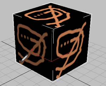
For example, you can use the Paint operator in Combustion. When you release the mouse, the stroke appears on the 3ds Max object.

Paint operator in Combustion
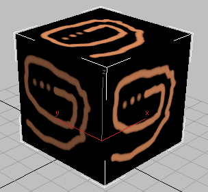
Painted object in 3ds Max
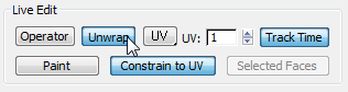
In the 3ds Max Material Editor, you can use the Unwrap Mesh feature to display your 3D object as a 2D mesh in Combustion. You can adjust the color and size of the mesh.
The mesh display is only an overlay to help you orient paint strokes and other Combustion effects. It is displayed in Combustion but is not a part of the composite or the map.
In Combustion, a mesh appears. This is an "unwrapped" projection of the 3D object.
3D object in 3ds Max
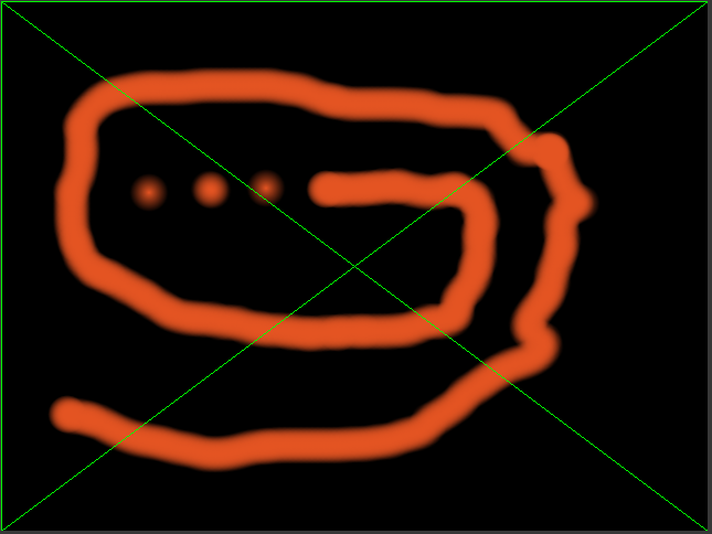
Corresponding mesh in Combustion
 Preferences Mesh.
 | Use | To |
|---|---|
| Anti-Alias Mesh | Remove jaggies from the mesh. |
| Display During Playback | Display the mesh when you play back the animation. |
| Color | Click the color box to set the color of the mesh using a color picker. |
To paint directly on the 3D object:
 Freehand
 Straight Line
 Rectangle
 Ellipse
In the 3ds Max viewport, a pen cursor appears. Drag the cursor over the object to paint on it.
When you release the cursor, the Paint object also appears in Combustion.
To animate Combustion Paint strokes:
Preferences. In the Preferences dialog select General, set Display Time As to Frames (From 0), and then click OK.
Now the time slider in 3ds Max controls the Timeline indicator in Combustion.
The Paint object appears on that frame in both Combustion and 3ds Max.
You can add Paint strokes in either program, but to modify them you must use Combustion.
To use an existing Combustion workspace as a material map in 3ds Max:
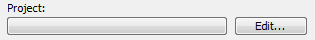
The Combustion workspace name and path appear in the Project button.
To apply the map to an object, drag the sample slot from the Material Editor to the object in a 3ds Max viewport.
To edit the map, click the Edit button in the Parameters rollout. In Combustion, the workspace corresponding to the selected map opens, and you can edit the image.
To paint geometry with a bitmapped material already assigned to it:
 (Pick Material From Object) so you can see the material in the Material Editor.
Combustion is launched and the Import Footage dialog appears. Import the same bitmap.
To paint on the bitmap, select Paint. You can also key or color correct the bitmap, or use it to build a composite. For more information, see the Combustion User's Guide.
(Show Standard Map In Viewport).
In the scene, the object is mapped in shaded viewports.
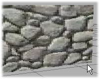
Object with original bitmap
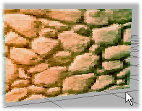
Object with painted bitmap
Use a Multi/Sub-Object material to control the location of your painting. Any sub-material can have a Combustion map, so you can use Combustion to affect only the selected faces.
If you are working with an editable mesh object, or a patch or NURBS surface, skip step 2. For geometry primitives, an option is to convert the object to a mesh, patch, or NURBS surface before step 3. However, you then lose the ability to adjust object parameters (for example, the radius of a sphere, the height of a box).
 (Pick Material From Object) to grab the material from the geometry.
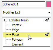
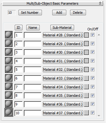
You now have a new Multi/Sub-Object material. The original material appears as a sub-material applied to the selected faces.
A Multi/Sub-Object material is simply a container for multiple sub-materials assigned to different faces of the same object. Click a Sub-Material button to go to a sub-material.
Material maps created in Combustion are vector-based and fully modifiable.
The workspace corresponding to the Combustion map opens in Combustion. As you modify the workspace in Combustion the map is updated in 3ds Max.
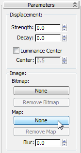
In 3ds Max, the Displace modifier acts as a force field to push and reshape an object's geometry. You can apply its variable force directly from the modifier gizmo, from a bitmap image, or from a Combustion workspace.
The grayscale component of the image is used to generate the displacement. Lighter colors in the image push outward more strongly than darker colors, resulting in a 3D displacement of the geometry.
In this example, the displacement is applied to a box primitive.
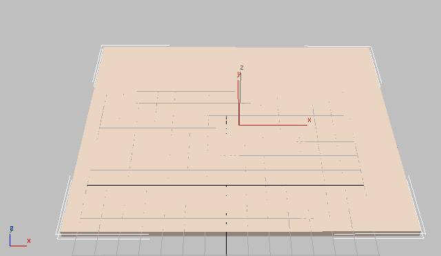
In the object's Parameters rollout, increase the number of Length and Width Segments. The closer the number of segments approaches the resolution of the displacement map, the more accurate is the result.
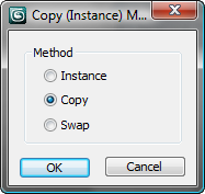
An Instance (Copy) Map dialog is displayed.
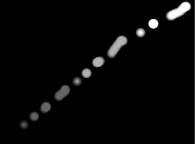
This launches Combustion. In the New dialog, set the Type To Paint, and create a grayscale image to use as a displacement map. For more information, see the Combustion User's Guide.
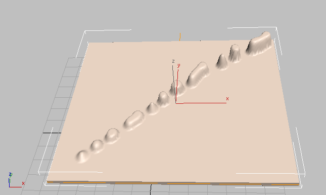
As you increase the strength, you can see the result of the displacement map on the selected object.
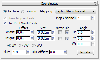
Like any 2D map in 3ds Max, mapping coordinates control how a Combustion map is positioned on objects.
For geometric primitives, mapping coordinates are usually provided automatically. For some kinds of geometry, such as meshes, patches, and NURBS surfaces, you must apply a UVW Map modifier to provide mapping coordinates.
Controls in a 2D map's Coordinates rollout affect how the map is positioned.
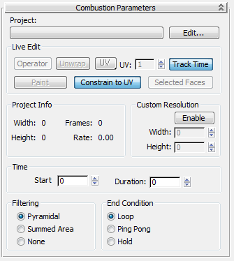
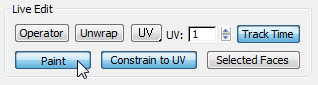
When you work with a Combustion map, these are the important points to remember:
These controls affect how you use Combustion with 3ds Max.
Switches control to Combustion, where you can select an operator. The results of the operator appear as the image in the Combustion map. The operator does not have to be the last operator in the pipe.
While Combustion is active, you can also adjust the operator. The Combustion map updates to show the results.
Takes the current UVW mapping coordinates of the currently selected 3D object (or the current Face sub-object selection), and displays them in Combustion. This can help you coordinate the map and the mesh as you paint. The Unwrap display is only an overlay. It is displayed in Combustion but is not a part of the composite or the map.
When enabled, constrains paint strokes to remain within the edges of the UV mapping coordinates. When paint strokes are unconstrained on an object such as a box, they can jump to the other side of the map when you cross a map’s edge. This can give erratic results. To prevent this, enable Constrain To UV.
In general, use the Constrain To UV option when you paint on boxes and other objects with planar maps. Disable this option when you want to paint on spherical maps or anywhere else the mapping has a singularity (where the edges of the map converge to a single point).
These readouts display the format of the Combustion Paint or composite operator. They are active when a Combustion workspace is loaded or Edit mode is active.
These controls relate frames in the Combustion workspace to frames in the Combustion map. See the controls under "End Condition Group" for how to handle the map when it contains fewer frames than the 3ds Max scene.


 Material Editor