In Action, you can create complex animations where movements applied to one node are passed down to all connecting nodes. The relationship between objects is referred to as a parent-to-child relationship where the parent node passes down its animations to its child object. The structure of one parent and one or more child nodes is referred to as a branch.
Use the Parent and Cut options in the Edit Mode box to change the parent-to-child relationship between nodes in the schematic. Parent mode makes an object the parent of another object. Cut mode removes the parent-to-child relationship between objects. Alternatively, when Auto Parent is enabled in the Action Setup menu, you can automatically parent objects in the schematic.
When you add certain nodes to the scene, a parent-to-child relationship is created automatically. For example, when you add a surface to the scene, it is automatically parented by an axis.


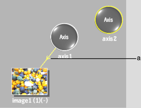
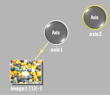
(a) An arrowed line indicates that axis1 is the parent of image1.
You can add an axis to the scene by itself, then make it the parent of another node. Use this method of parenting additional axes to create complex animations.
For example, create a cube of surfaces by parenting three additional axes to the same surface. Each axis that is parented to a surface places an additional surface in the scene. By changing the position and rotation of each axis, you can create a cube. If you parent the axes with another axis, you can control the position, rotation, scale, and shear of the cube.
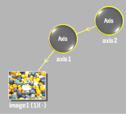
Axis2 becomes the parent of axis1, as shown in the After figure.
Before: The schematic shows axis1 as the parent of image1 |
After: Axis2 is made the parent of Axis1 using Parent mode |
Any transformations applied to axis2 are applied to axis1 and its surface (image1). If axis1 has any transformations, they are added to the transformations from axis2. For example, if axis2 is set to 500, 100, 0 and axis1 is set to -50, 20, -30, the positions are accumulated and applied to the surface. In this case, Image1 is positioned at 450, 120, -30.
You can override the transformations passed from a parent to a child by enabling the Free button in the Axis menu.