You can group nodes to simplify cluttered schematics. When you group nodes, they collapse into one group node that you can use as a parent to, or child of, other clips and nodes. A group is represented by a single node that displays the group contents, inputs, and outputs.
You can create several groups and organize them in your schematic. You can then work on individual groups. For example, group a Keying and Colour Correction branch separately from an Action and filtering branch, and then work on each branch independently of the other. If you need to edit the nodes in a group, you can expand the group and make the necessary modifications.


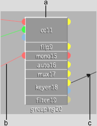
(a) Group node (b) Input connection (c) Output connection
A group is a dynamic node that you can customize using the Group List menu. The Group List menu lists all the nodes and connections contained in a group and lets you rename or hide them. In addition, you can define which input and output connection sockets are visible and available for connection in the schematic.
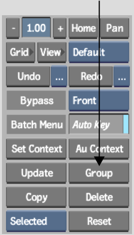
The selected nodes collapse into a group node.
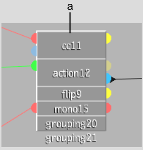
(a) The Group node lists the nodes contained in the group, as well as the non-hidden input tabs and output tabs
You can select a node in the Group List menu to display the group at the selected node's stage. The View box must be set to Result, Front, or Back to use this display option.
Use the grouping controls to adjust the contents of a group.
When you select a group node, the Process Tree controls change to show the List button, and the Group List menu displays the Ungroup, Edit buttons, and the Sort Order buttons.
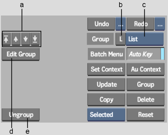
(a) Sort Order buttons (b) List button (c) Node List box (d) Edit Group button (e) Ungroup button
Defining Group Display Settings
You can customize the group node using the Group List menu.
To define a group's display settings:
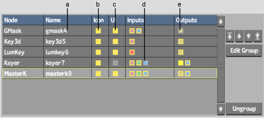
(a) Node name (b) Enabled icon visibility (c) Enabled UI visibility (d) Disabled input visibility (e) Disabled Output visibility
| Click: | To: |
|---|---|
| Name | Change the node's name. |
| Icon | Toggle the node's visibility within the group. |
| UI | Toggle the node's availability in the Node List box. |
| Input | Hide or unhide the selected node's input sockets. Sockets are colour-coded with the same scheme as Batch nodes. |
| Output | Hide or unhide the selected node's output sockets. Sockets are colour-coded with the same scheme as Batch nodes. |
In addition to the standard node bins are two bins that can contain custom nodes. You can drag nodes, groups, branches, and whole Batch trees into a custom node bin to create a custom node. A custom node can consist of a single node, like a specific Colour Correct you need to use frequently, or a multitude of nodes that create an effect, such as a Keyer node parented to an Action node with layers connected to a GMask node. The newly created custom node can then be pulled out of the node bin and into a schematic work area to be used anywhere in Batch as often as you like.
The selection is copied to the bin. The original selection remains in the schematic. If the selection is dropped outside of the bins, the selection is deleted.
User custom node bin
A node appears with the same configuration that was used to create the custom node.
You can use custom nodes as often as you like. Each time a custom node is dropped into the schematic work area, it is given a new name and/or number.
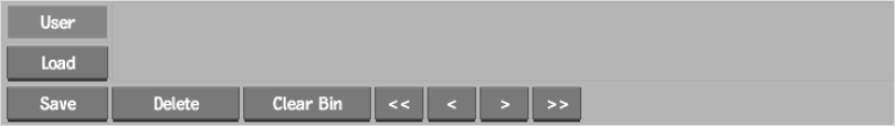
To manage the custom node bins:
| Click: | To: |
|---|---|
| Load | Load custom nodes from another project or user. |
| Save | Save the current custom nodes so they can be loaded by another project or user. |
| Delete | Delete the selected custom node. |
| Clear Bin | Delete all custom nodes in the node bin. You must confirm the multiple deletion. |
| Arrow Buttons | Reposition custom nodes in the bin. The single arrow button advances one node at a time, and the double arrow button brings you to the first or last custom node. |
A node's bit depth and resolution are not always compatible. It is not always possible to use clips of different resolution or bit depth. For example, it is not possible to have one custom Colour Corrector node with an 8-bit clip and another with a 12-bit clip. Garbage masks, on the other hand, work correctly with clips of different bit depth, but not of different resolutions.


