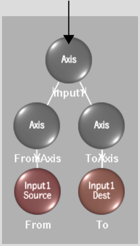
In the Distort schematic, a node can be a spline or an axis. A node exists for each spline in the scene, along with Axis nodes used to control properties of splines from the Axis menu.
You work with nodes to create parent-to-child relationships between splines, and to easily select splines. As well, nodes help you organize warps that occur between corresponding source and destination splines in a spline node tree, and morphs that occur between linked Input1 and Input2 source nodes in different spline node trees.
Warps occur between corresponding source and destination splines that are offset from one another |
Morphs occur between corresponding Input1 and Input2 source splines that are linked together |
When you add a spline to the Input1 or Input2 clip, axis and spline nodes are added to the Distort schematic. These nodes represent the source spline and its corresponding destination spline, and are parented to axes in a spline node tree.
Warps are created when the source spline and destination spline in a spline node tree are offset from one another.
Morphs are created when you link a source spline from an Input1 spline node tree to a source spline from an Input2 spline node tree.
Use Axis nodes to control the position, rotation, scale, and shear values of splines.
Initially when you add a spline, its source and destination node is parented to its own Axis node, and these Axis nodes are in turn parented to a common Axis node. So, for example, you can control the position of a particular Input1 source spline via its Axis node. Click the Axis node, the direct parent of the Spline node, then use the Axis menu in the Distort module to apply tracking data to the node.
If you want to affect both a source spline and its corresponding destination spline, you can use the Axis node at the top of the spline node tree.


Although when you add splines, they are initially parented to their own spline node tree, you can add more Axis nodes to the schematic, and parent splines from different spline node trees to the same Axis node. This can be useful, for example, if you create splines for the different features of an actor's face and want them to move in tandem with the actor.
Axis nodes for corresponding splines can be unlinked from each other by selecting a spline's axis node, then selecting Enable Warping from the Link box.
Use the Spline node to select the spline itself, including all its points. Each spline added to the schematic results in a source and destination Spline node. Each Spline node is representative of a particular spline, which consists of a closed shape defined by vertices. If Link Src and Dst is selected from the Link Box, transformations applied to a source or destination spline also affect the corresponding spline. This does not apply when Input1 and Input2 source splines are linked for source interpolation. See Linking Source Nodes.
When you add a spline, it is applied to the Input1 or Input2 clip, depending on what is selected in the Input box. You can then select it and change it from an Input1 to an Input2 spline, or from an Input2 to an Input1 spline. This changes the input for both the source and corresponding destination spline. See Toggling Spline Nodes from One Input to Another.
You can add more Axis nodes to the schematic and link the spline nodes to them, for example, if you want to affect the children splines in the same way.
You can, for example, track all the points for the selected spline using the Stabilizer. You can also select the Spline node for a spline if you are having trouble distinguishing between splines in a complex setup.