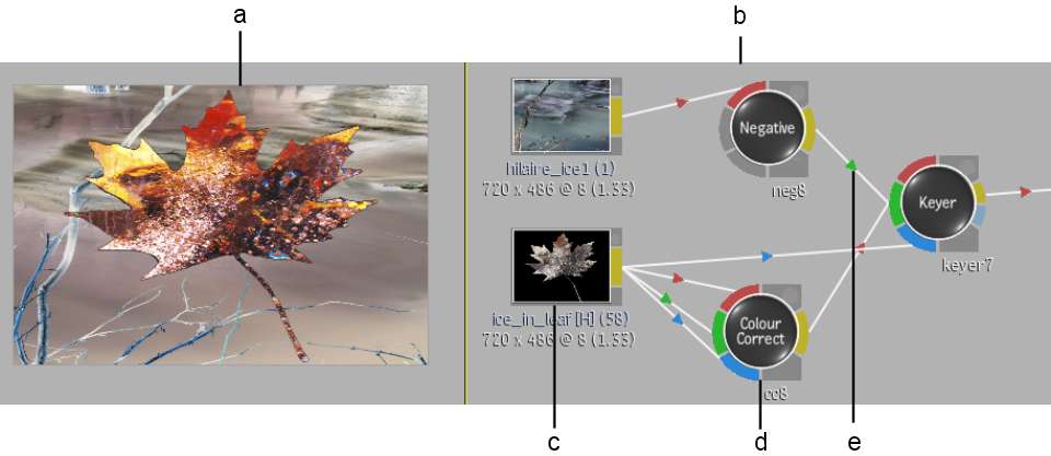
In the Batch and Modular Keyer flow graph schematics, you build process trees of clips and nodes to create an effect. A node represents a function or module that affects a clip or another node in the process tree. The result of each operation serves as the source for the next one.
In the following Batch example, the result of the Negative and Colour Correct operations feed into the Keyer to create the composite. The result of the Keyer composite feeds into the Output node where the final result is processed.


(a) Result view (b) Schematic view (c) Clip feeds into Colour Correct node (d) Colour Correct node feeds into Keyer node (e) Arrow direction indicates result of Negative node feeds into Keyer node