Chapter 15, Secondary Colour Grading
| Adding a Split Screen | Changing the Priority Order of Geometries | ||
Chapter 15, Secondary Colour Grading |
|||
By default, every geometry you draw has an axis. Each geometry and its axis are displayed in the Player.
 "Show full-size image")
|
You use the Axes list to add and delete axes, as well as parent multiple axes to a master axis. You use the schematic view to create parent/child connections among shapes and axes.
A parent axis allows you to move, scale, rotate, and track multiple geometries.

The Axes list appears in almost all Lustre menus and provides a list view of geometries and their axes.
 "Show full-size image")
|
|
|
|
When you select the axis or the geometry in the Axes list, it is also selected in the Player. The inverse is also true.
In the Axes list, select the axis you want to parent. To select multiple axes, Shift-click each axis.
Click Add Axis.
The axes you selected are now parented to a new master axis.
In the Axes list, select the axes you want to delete. To select multiple axes, Shift-click each axis.
Click Del. Axis.
The axis is deleted from the Player and the Axes list.
As an alternative to using the Axes list to view the axis hierarchy and create parent axes, you can use the schematic.
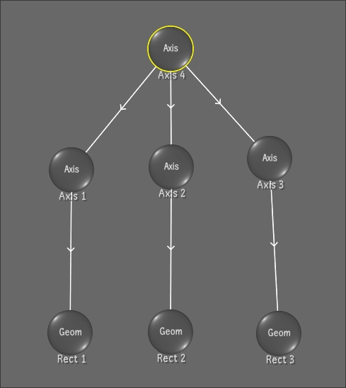
 "Show full-size image")
The schematic appears in the Player and allows you to parent shapes and axes in any combination you like. For example, a shape could parent an axis, or vice versa.
Creating a master axis and using it to parent multiple axes simultaneously is performed the same way as when using the Axes list. However, in the schematic, you can also make connections one at a time.
Note: Axes cannot be deleted in the schematic.
Press the tilde key (~) to switch to a schematic view of the axis hierarchy.
Note: To pan within the schematic, hold down the middle mouse button and drag.
To connect one item to another, click just inside the border of the parent object and drag to the intended child object. The connection is represented by a white line (yellow when selected), with the hierarchy indicated by an arrow that points away from the parent object and towards the child.
Note: To move an item, click in its centre and drag. To break a link, drag a red line across the connection line.
Switch back to default view by pressing ~ again.
The changed hierarchy is displayed in the schematic.
