


Adding a Deformation Mesh
When you add a Deform node, the deformation mesh appears over the 3D text or object. You can view the source mesh, the destination mesh, or both to assist you as you deform the object. You can also turn both meshes off to view only the deformed object.
The deformation mesh consists of cells and lattices. You can divide the mesh into 1-100 lattices and each lattice can be divided by 1-3 cells. Increase the number of cells and lattices to deform specific areas of the object.
To add a deformation mesh:
The deformation mesh is added to the selected object.


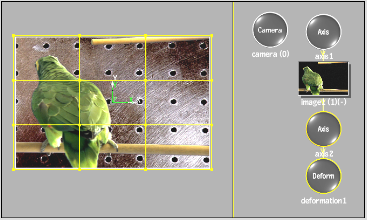
Image courtesy of Quietman
If you do not see the deformation mesh, follow the next steps.
The Deform menu appears.
