Use the schematic controls to move, parent, unparent, link, copy, or delete nodes.


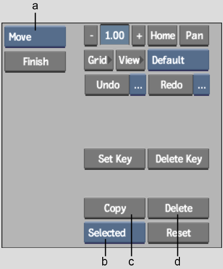
(a) Edit Mode box (b) Selection Mode box (c) Copy button (d) Delete button
Before you can edit or animate a spline or axis in the schematic, you must select its node.
To select a node:
Use Move mode to move nodes in the schematic. Moving the nodes in the Distort schematic has no effect on the relationships between nodes, nor does it affect the position of the splines in the scene.
To move a node in the schematic:
To move a node and its children, press and hold the Alt key while dragging the parent. For example, you can drag a spline node tree by Alt-dragging its top Axis node.
You can remove nodes from the schematic using the Edit Mode box or the Delete button.
To delete a node using the Edit Mode box:
The node is removed from the scene.
To delete objects using the Delete button:
| Select: | To: |
|---|---|
| Selected | Delete the currently selected node. For example, this option deletes a spline node without deleting its parent axis, or an axis without deleting its spline node. |
| Branch | Delete the selected node and all its children. |
| All Nodes | Delete all nodes in the scene. |
Use Move mode from the Edit Mode box to change the parent-to-child relationship between nodes in the Distort schematic. By using Move mode, and dragging from one node to another, a node becomes the parent of another node. You can also use Move mode to remove parent-to-child relationships between nodes by dragging across the line linking them in the schematic.
Use Move mode when you create branches. See Creating Branches.
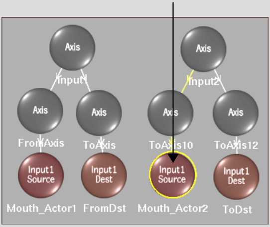
Toggling Spline Nodes from One Input to Another
Morphs work best when the source spline and destination spline have the same orientation—that is, were both drawn clockwise or counterclockwise—and the same number of vertices. You can ensure this is the case by drawing your spline on one input, then copying it to the other. To do this, first copy the spline, and then “move” the copy using the Morph menu's Toggle Input button. It toggles the selected spline from one input to the other.
To toggle a Spline node's input:
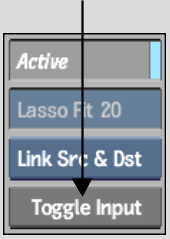
The source and destination spline nodes change either from Input1 to Input2, or from Input2 to Input1.
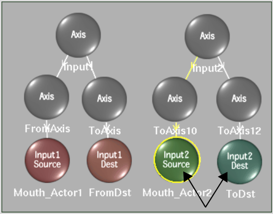
You link a spline source node from Input1 to a spline source node from Input2 to create interpolation between them for a morph. Destination splines are no longer used and cleared from the schematic. The source of the Input2 spline node tree becomes the destination of the Input1 spline node tree.
You can create as many relationships between Input1 and Input2 spline nodes by linking them in the schematic, as there are features to correlate between the clips.
To link source nodes:
The splines are linked to each other, as indicated by the blue dotted connector lines. The destination splines, and their respective Axis nodes, are removed from the two spline node trees. Once Spline nodes are linked, you can set an interpolation value to determine the percentage that the feature defined by the Input1 spline mixes with the feature defined by the Input2 spline. See Interpolating Features.
To unlink nodes:
The spline nodes are unlinked, and the destination splines and their axes reappear for each of the affected spline node trees.
Use the Copy button to copy an object, a branch (object and its children), or all.
To copy a single object or branch:
| Select: | To: |
|---|---|
| Selected | Copy the currently selected object. |
| Branch | Copy the selected object and all its children. To avoid copying objects by mistake, use the Schematic view to determine which objects you are copying. |
| All Nodes | Copy all objects in the scene. |


