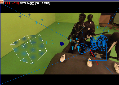
The 3D View shows the following from an arbitrary viewpoint:
- Cameras
- Tracking information
- Point Labels, showing the point names.
- 3D Markers, or 3D Helpers, displaying the estimated 3D points as customizable 3D Helpers (cones, pyramids, crosses). A link is drawn
between the 2D reprojections and the corresponding 3D points if available.
- Manipulator Axes
- A 3D planar Grid
- Non-physical objects: Lights and Relations
- Built-in contours
- The estimated Camera Path
- The reference coordinate system
- 3D objects created directly in MatchMover or imported. See Working with 3D objects.
The default 3D View is in the Free Camera mode with the image plane displayed. By clicking on the image plane, you are able to tweak its displayed depth by using the
displayed translation manipulator.
Toggle the image plane display by selecting Display > Background Image.
In the 3D View window you can switch to Lock on Camera mode. See Lock on Camera mode. The view constrains the camera to see the image as the background.
When you place a 3D object within the 3D View window, MatchMover provides manipulators that you can use to edit them. See Editing 3D primitives and objects.
Note To change the color of the 3D View background, the camera, or the camera path, select Edit > Preferences, click the Color tab in the User Preferences window, and change the color of the corresponding sample box.
You can create tracks in the 3D View in the same way as in the 2D View. See Working in 3D mode.
Displaying the 3D View attributes
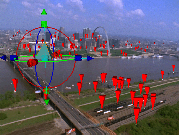
By default the 3D View shows a grid and axes with a perspective viewing, the camera path with its corresponding image plane, and the reconstructed
points.
You can display or hide points’ attributes by either:
- Selecting Display from the main menu then clicking on the attribute in the pop-up menu.
- Right-clicking in the 3D View and selecting Display and an attribute from the pop-up menu.
For Point Labels and 3D Marker Styles attributes, a single diamond defines that the attribute is displayed for the selected point.
If you click again, two diamonds appear beside the attribute defining that the selected attribute is displayed for all points.
No diamonds means that this attribute is not displayed.
For all other options, a check mark beside the option indicates that the option is active. Clicking the option again hides
the check mark and deactivates it.
You can also toggle the 3D object display in the Display menu:
- Flat shading
- Wireframe. A backface culling option for wireframe mode also exists in the Display menu.
-
Transparent
- Texture mode.
TipThe default shading is smooth. See the Preferences window to change it to real flat shading.
Select Display > Inliners to show only the 3D points that are defined in 2D at the current frame.
Changing the number of wireframe divisions
You can change the number of divisions in the wireframe of a selected object in the 3D View mode.
- Select the Project tab in the Parameters window.
- Enter a number in the 3D Primitive Resolution text field. A smaller number reduces the size of the intervals in the wireframe grid; a greater number decreases their size.
Changing the size and shape of the 3D Helpers
To change the size of the 3D helpers:
- Select the Project tab in the Parameters window.
- Select a 3D Helper Shape from Cone, Pyramid, or Cross. Select Cross for a better feedback of the 3D helpers’ orientation.
- Enter a number in the 3D Helper Size text field. A smaller number reduces the size of the 3D Helpers; a greater number increase their size.
NoteTo change the color of a 3D point or the selected 3D point, select Edit > Preferences, click the Color tab in the User Preferences window, and change the color of the corresponding sample box.
Changing the Grid Step
By default, the 3D Grid Step has a value of 10. You can change this value in the Subdivisions text field in the Project tab in the Parameters window.
Lock on Camera mode
The Lock on Camera mode allows you to insert virtual objects and constrains the computed camera to view the image sequence as the background.
It can be considered as a 2D view with superimposed 3D objects.
The Lock On Camera mode allows you to display the same attributes as the Free Camera mode.
To lock on a camera:
- Make sure that you are in the 3D mode.
- Do one of the following:
- Select View > Lock On Camera.
- Right-click in the 3D View window and select Lock On Camera from the pop-up menu.
- Click the Lock on Camera icon
 in the Navigation toolbar.
NoteAs the Lock on Camera mode includes the image sequence, you are viewing the scene from the position of the estimated camera. Unlike the Free Camera mode, you cannot rotate or the scene to view it from a different position.
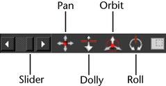
Navigating in the 3D View
You can access the navigation options in the 3D View in the View menu or in the Navigation toolbar located at the bottom of the Workspace.
Use the slider to scroll through the images.
Alternatively, you can use the following shortcuts and dragging the pointer.
| Action |
Shortcut |
Pointer |
|
Changes the current time
|
Ctrl+click
|

|
|
Dolly
|
Alt+Ctrl+click
|

|
|
Fit to rectangle
|
Alt+Shift+click
|

|
|
Move to next frame
|
Ctrl+right arrow
|
-
|
|
Move to previous frame
|
Ctrl+left arrow
|
-
|
|
Orbit in the Free Camera mode
|
Alt+right-click
|

|
|
Pan
|
Alt+click (or scroll bars)
|

|
|
Zoom
|
Alt+Ctrl+right-click (or "+" or "-")
|

|
NoteBy right-clicking in the 3D View, you can turn the camera toward the selected item by selecting View > Look At from the pop-up menu.