MatchMover manages a set of user-defined coordinate systems with respect to which the cameras and 3D points are expressed. If no coordinate system is specified, MatchMover chooses an arbitrary one. You can define a coordinate system in order to facilitate the manipulation of your exported project in a 3D package. If no point relations have been set up, MatchMover aligns the coordinate system on the computed position of the camera for the first frame; the default is the camera looking towards Z and Y as Up axis, but this changes according to your project’s 3D parameters if you selected a different up axis.
If no coordinate system is defined, MatchMover tries to create one from the point relations or the survey points you defined (it needs at last 4 non colinear survey points to do so).
There are two main advantages in defining a particular coordinate system, described below.
Advantage 1 - It makes manipulation easier and more intuitive in the next stages, when virtual objects are inserted in the scene. For example, if a virtual object such as a car has to be placed on a flat surface, e.g., a road, it is very helpful to have two coordinate axes, e.g., X and Y, in the plane of that surface.
Advantage 2 - It allows you to impose strong constraints on the computed 3D points and the camera move, based on clear alignments in the scene inferred from the image sequence.
For example, two points that are at the same height above the floor, where the X and Y coordinate axes lie, have the same Z coordinate. These constraints help the system to compute data that is more accurate and closer to reality. In practice this applies to a lot of cases such as house walls and floors, any flat surface etc.
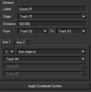
To set a 3D coordinate system, you specify two directions. Each direction is defined as one of the following:
The coordinate system is then defined in 3 steps.
You can define a coordinate system to the scene using two methods:
Defining the coordinate system using the Parameters Window
See Selecting tracks.
By default, no points are selected and all the points will appear in the list. However, if there is a long list of points, you might find it difficult to select from such a long list. That’s why there is a way to pre-select points.
The coordinate system is now defined and the coordinates you set are listed in the Coordinate Systems folder in the Project window.
Defining a coordinate system using the Coordinate System Manipulator
The Coordinate System Manipulator makes creating the coordinate system easy. The manipulator is displayed in the 3D View whenever a coordinate system is selected or a new coordinate system is created.
You can drag and snap the vertices of the manipulator’s three axes (red: X-axis, green: Y-axis, blue: Z-axis) to 3D points in the scene and use the independent, light blue distance line for determining the scale of the scene by measuring the distance between two points.

To create a coordinate system:
To change the color of the manipulator axes and distance line, select Edit > Preferences, click the Color tab in the User Preferences window, and change the color of the corresponding sample box.
When an axis is defined as “1st axis” or “2nd axis”, it is locked, meaning that although it can be moved and snapped to another point, it still retains its quality of being first or second axis.
The origin can also be moved and snapped to a different point, and although the manipulator’s axes remain in the same direction, they are now defined between two points instead of being defined from the former origin to their snap point.
To delete a coordinate system, do one of the following:
When you have created several coordinate systems, you can select one to define the world reference, shown by the three axes in the bottom left corner of the Workspace.

Mapping the coordinate system to a camera
You can also center the coordinate system on a camera at the current frame by selecting 3D Scene > Map World on Camera. This defines the coordinate system from the computed camera at the current frame so that the origin is at the optical center and the axes are that of the camera (Z is the optical axis and Y is the up axis).


