Set up the trackers and
the survey points
You can use survey points to analyze the results of 3D tracking and to isolate specific frames or points where adjustment may be necessary.
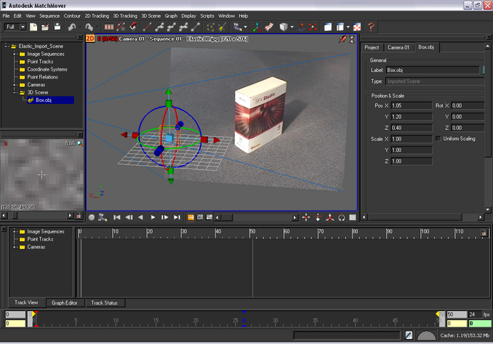
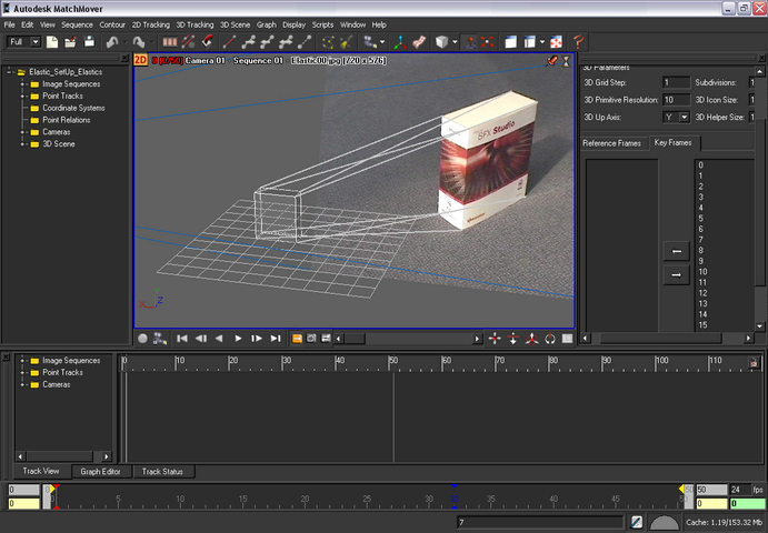
For example, set up your viewing position and angle similar to the image below.
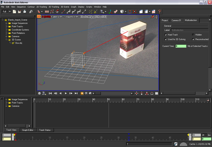
As you drag the curser toward the image plane, a red elastic line follows, joining the selected vertex and the image plane.
The elastic is now blue and a new track, Track 01, is created with a point in the current frame (visible in the track view).
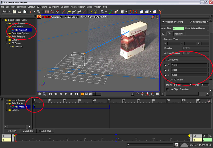
Survey point information issued from the selected vertex is automatically associated to the track. You can see this information in the Parameters window under the Track 01 tab. Click the 3D tab and look in the Survey Info section.
You can check the quality of the new track by playing the sequence.
To get a close-up view of the tracking point, you can lock the sequence play to the Magnifier window. See Supervised 2D tracking.
Your project should now look similar to the image below.
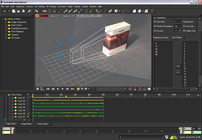
Solve and check the tracking results
To solve and check the tracking results
After the camera completes the solve, blue cones appear at the tracking points on the 3D object and the new tracks appear in the Track window.
When you look in the Track window, notice that some of your new tracks have yellow segments, indicating that acceptable, but not good tracking. This occurs because the constraints induced by the 3D points are quite strong, while the footage quality does not allow the points to reach a high accuracy on the 2D points locations.
The Workspace view now displays the cameras perspective.