Soft/Rigid Bodies >
Create Active Rigid Body
Soft/Rigid Bodies >
Create Active Rigid Body > 
Sets the options when creating an active rigid body. The options are:
By default, you cannot break connections from the rigid body to the rigid body solver that handles its dynamic animation. You can turn on Allow Disconnection so that you can break the connections. See Warning when you delete rigid body connections. Available in Attribute Editor only.
Sets the mass of an active rigid body. The greater the mass, the greater the influence on objects it collides with. Maya ignores the mass attribute of passive rigid bodies.
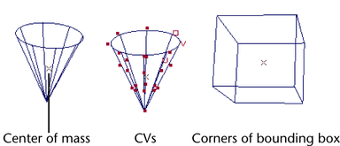
Specifies the position of an active rigid body’s center of mass in local space coordinates. An x-shaped icon represents the center of mass. It’s easiest to see in wireframe mode.
The center of mass affects how an active rigid body bounces. For example, suppose you place a sphere’s center of mass below and to the side of the sphere’s surface. If you make the sphere fall with gravity and collide with a passive rigid body NURBS plane, the sphere bounces and bobbles around the center of mass.
The center of mass also sets the point about which an active rigid body rotates when you set the Initial Spin (described later). For example, if you set the center of mass within an active rigid body sphere, the rigid body spins about itself. If you set it outside the sphere, the sphere rotates about the center of mass.
By default, a polygonal object’s center of mass is the centroid of its bounding box. A NURBS object’s default center of mass might be slightly away from the centroid.
Maya doesn’t use the center of mass in dynamic calculations of passive rigid bodies.
Sets how much a rigid body resists moving from resting contact with another rigid body. For instance, if you place a ball on a sloped plane, Static Friction sets how easily the ball begins its initial slide or roll down the plane. Static friction has little or no effect after an object is moving.
A value of 0 lets the rigid body move freely. A value of 1 diminishes movement.
Sets how much a moving rigid body resists movement against another rigid body’s surface.
A value of 0 lets the rigid body move freely. A value of 1 diminishes movement.
Creates an instantaneous force, with magnitude and direction, on the rigid body at the local space position specified in Impulse Position X, Y, Z. The higher the number, the greater the magnitude of force. For more details, see Keying impulses to rigid bodies.
Specifies the position in the rigid body’s local space where the impulse strikes. If the impulse strikes a point other than the center of mass, the rigid body rotates about its center of mass in addition to moving with the change to its velocity.
If you specify a position outside the object’s surface boundaries, you’ll still see rotation and velocity. Note that the 0, 0, 0 position of an object’s local space is at the center of its bounding box.
Applies an instantaneous rotational force (torque) on the rigid body’s center of mass in the direction you specify by the X, Y, and Z values. These values set magnitude and direction. The higher the number, the greater the magnitude of the rotational force.
Displays a menu that lets you select a simple internal cube or sphere as a stand-in for rigid body calculations. The original object remains visible in the scene. If you use a stand-in sphere or cube, playback speed improves but collision reactions differ from the actual object. To use the actual geometry, select none.
Maya internally converts NURBS objects to polygons before it animates rigid body dynamics. The Tessellation Factor sets the approximate number of polygons created during the conversion. Lower numbers create coarser geometry and lessen animation accuracy, but increase the playback speed.
Increase the Tessellation Factor if you are bouncing an object on a bumpy, irregular surface. Experiment with various values until you see the desired result.
If you change the Tessellation Factor, the internal conversion occurs once, immediately after you change its value. This takes some time for complex NURBS surfaces. Increasing the Tessellation Factor increases the time for Maya to detect rigid body collisions.
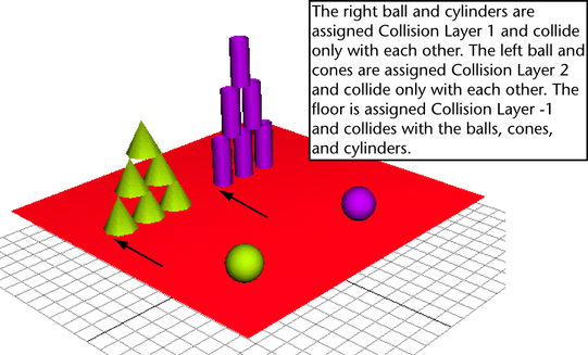
You can use collision layers to create exclusive groups of objects that collide with each other. Only rigid bodies with the same collision layer number can collide with each other.
For example, suppose you have four objects moving towards each other, but you want one of the objects to pass through without colliding. You can assign the non-colliding object a different collision layer number.
By putting rigid bodies that don’t collide in different collision layers, you can lessen collision processing time.
A rigid body in collision layer -1 (minus 1) will collide with all rigid bodies in the solver, regardless of their collision layer numbers.
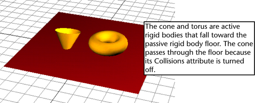
When off, the rigid body doesn’t collide with any objects in a scene.