Show in Contents

Add to Favorites

Home: Autodesk Maya Online Help

Create a Muscle Direction object

Skin Deformation

Set up Force deformation

Set up Displacement deformation
If
you want to use the cMuscleDisplace node as a deformation feature,
you can create a displace node and connect it to a Muscle deformed
object.
After creating or connecting a cMuscleDisplace
node, you may want to adjust its attributes to get the desired effect.
See
cMuscleDisplace node for
descriptions of the attributes. Since Displacement nodes are distance-based
(that is, they falloff or have more effect as they approach or move
away from the surface) there are no weights to paint.
Related topics
To
set up a displace node for deformation
- Select
Muscle > Displace > Create Muscle Displace from
the main menu bar.
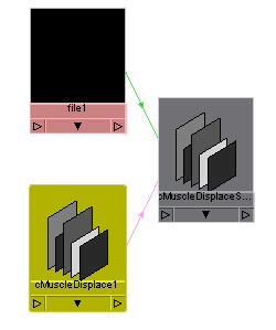
A new cMuscleDisplace node is created and selected.
By default, this node is a planar-style displace node. This displace
setup not only includes the group node and cMuscleDisplace locator
shape, but also a file input for selecting the file texture. You
can see this by graphing the selected displace node in the Hypershade or Hypergraph.
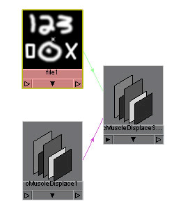
- Select
the file node going into the cMuscleDisplace shape and select an image
file to use as the texture. Typically, you select the node, go to
the Attribute Editor, and click
the folder icon next to the Image Name field
to browse for an image file to use.
NoteAdvanced users can also create any traditional
Maya 2D texture and connect the shader’s outColor into
the displace node dispData.shader attribute instead
of using a file texture node.
The image should be black where you want no
effect, and white where you want the displacement to push out or
occur.
- Change
the attributes of your cMuscleDisplace node as needed and connect
it to a Muscle deformer.
For example, you can change the cMuscleDisplace
node from Planar mode to Cylindrical,
or set other options.
To
connect a cMuscleDisplace node
- Select
one or more cMuscleDisplace node objects, then select one or more Muscle
deformed objects (objects with the Muscle skin deformer applied). (The
order of selection does not matter.)
- Select
Muscle > Displace > Connect selected Muscle Displace nodes.
The nodes are now connected.
- Select
the Muscle deformed object and find the cMuscleSystem deformer node
in the Channel Box or in the Attribute
Editor.
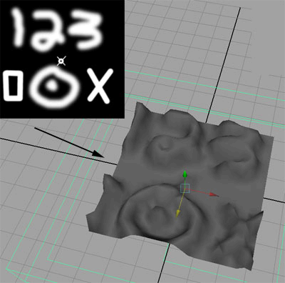
- Set
the Enable Displace attribute to on.
You can now see the displacement effect. You
may need to move, scale or change other settings on the cMuscleDisplace
node to see the effect.
When you no longer want to use a displacement
node, you can disconnect it from the cMuscleSystem deformer.
To
disconnect a displace node
- Select
one or more cMuscleDisplace nodes and one or more Muscle deformed
objects. (The order of selection does not matter.)
- Select
Muscle > Displace > Disconnect selected Muscle Displace nodes from
the main menu bar.
The item is disconnected, and no longer affects
the mesh.
Connect a NURBS Curve to a cMuscleDisplace node
When
the cMuscleDisplace mode is set to Curves, the
position and image map on the displace node no longer matter, and
instead NURBS curves that are connected to the node are used to
do the displacement. As the curves approach the surface, they move
the points out.
NoteThis feature works for deformation-based
displacement, and Maya shader displacement, but is not supported
with the mental ray version of the shader.
In order to use this feature, you must connect
NURBS curves into the cMuscleDisplace node. You can select one or
more curves, but the radius/falloff of them will be the same and
is set from the cMuscleDisplace node it is connected to. If you
want to use different radius/falloffs, you must use multiple cMuscleDisplace
nodes.
To
connect a curve
- Draw
a NURBS curve or curves using standard Maya curve tools.
- Create
a cMuscleDisplace node as described in
Set up Displacement deformation.
- Select
one or more curves and a cMuscleDisplace node.
- Select
Muscle > Displace > Connect NURBS Curve to Muscle Displace from the
main menu bar.
The curves are now connected. The displacement
node itself should be connected to the Muscle deformer, or as part
of a shading network. See
Create Maya cMuscleShader network.
- Switch
the cMuscleDisplace mode to Curves.
The curves are now used to deform the surface.
To
disconnect a curve from a cMuscleDisplace node:
- Select
the NURBS curve(s) and the cMuscleDisplace node.
- Select
Muscle > Displace > Disconnect NURBS Curve from Muscle Displace.
The curve is disconnected and no longer affects
the deformation even if the node is in Curves mode.
Create Maya cMuscleShader network
The
cMuscleDisplace feature can operate as a shader as well as a deformation tool.
To do this, a special cMuscleShader node for Maya is created that
does displacement and handles a connection from a cMuscleDisplace
node. This shader is then connected to the material for your object.
The cMuscleShader is a shader designed for the internal Maya renderer.
To
set up a node for Maya-based cMuscleDisplace shading
- Create
a basic material and apply it to your mesh.
- Select
Muscle > Displace > Create Maya Muscle Shader Network from
the main menu bar.
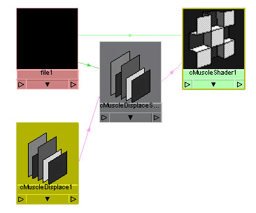
A new cMuscleShader and a new cMuscleDisplace
node are created and selected.
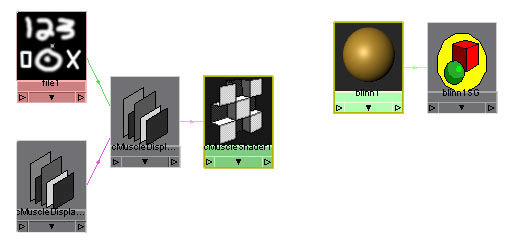
- Open
the Hypershade and graph the selected
objects.
- Select
the file node going into the shader and select an image file to
use for the displacement. The image should be black where you want
no effect, and white where you want it to displace the geometry.
- Select
the cMuscleDisplace shader node and your main Maya material and graph
them in the Hypershade.
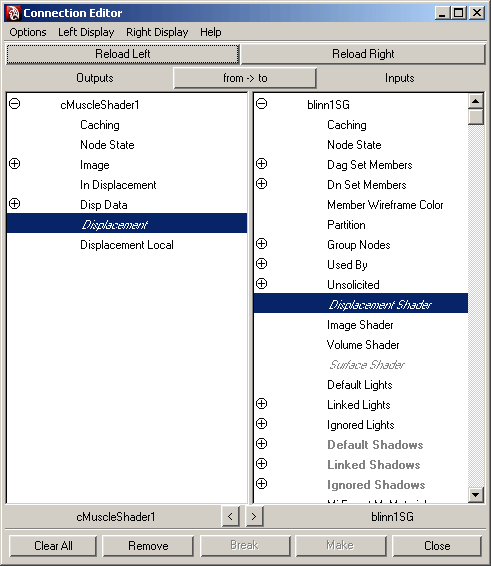
- Drag
the cMuscleShader onto the Shading Group for the material and select
“other” from the menu that appears.
The Maya Connection Editor appears.
- From
the shader on the left, select Displacement and
connect it to the Displacement Shader on the
right side.
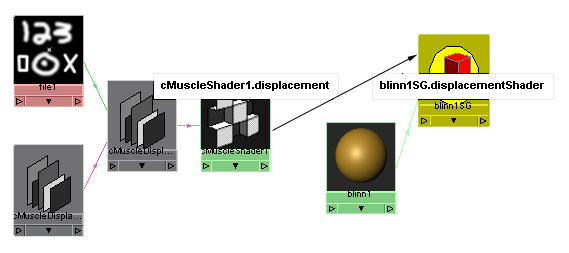
- Close
the Connection Editor.
Now you can see the connection from the shader
into the shading group.
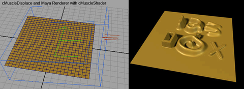
- Use
the Maya renderer to see the effect. You can use typical Maya adjustments
to increase the displacement quality. For example, you can select the
mesh and increase the number of Initial and Extra displacement samples
in the Displacement Map section of
the Attribute Editor for your mesh.
Create a mental ray mib_cMuscleShader network
The cMuscleDisplace feature can operate as a
shader as well as a deformation tool. For mental ray rendering,
a special mib_cMuscleShader node is created that does displacement
and handles a connection from a cMuscleDisplace node. This shader
is then connected to the material for your object.
To
set up a node for mental ray-based cMuscleDisplace shading
- Create
a basic material and apply it to your mesh.
- Select
Muscle > Displace > Create Mental Ray mib_cMuscleShader Network from
the main menu bar.
A new mib_cMuscleShader and a new cMuscleDisplace
node are created and selected.
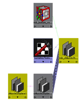
- Open
the Hypershade and graph the selected
objects.
- Select
the mentalray_Texture node going into the shader and select an image
file to use for the displacement with the Attribute Editor.
The image should be black where you want no effect, and white where
you want it to displace the geometry.
- Select
the cMuscleDisplace shader node and your main Maya material and graph
them in the Hypershade.
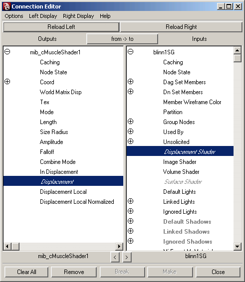
- Drag
the cMuscleShader onto the Shading Group for the material and select
“other” from the menu that appears.
The Maya Connection Editor appears.
- From
the shader on the left, select Displacement and
connect it to the Displacement Shader on the right.
- Close
the Connection Editor.
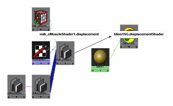
Now you can see the connection from the shader
into the shading group.
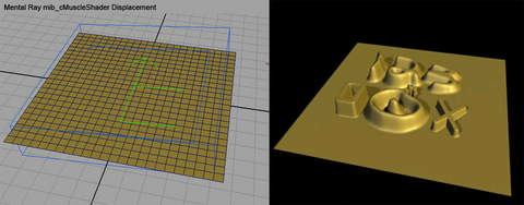
- Render
the scene with the mental ray renderer to see the effect. You may want
to use typical Maya mental ray adjustments to make higher quality displacement.
For example, in the mental ray tab
of the Render Globals dialog box,
you can expand the Render Options and then the Overrides section.
In that section, for Tessellation, you can click
the texture icon to create a new mentalrayDisplaceApprox node for
rendering this scene. In the Attribute Editor you
can then set this to a Spatial approximation
method, Fine approximation style, and
increase the Max Subdivisions as desired.