Learning Resources > Tutorials > Getting Started with Maya > Polygonal Modeling > Lesson 1: Modeling a polygonal
mesh >
Editing components in the
perspective view
Repositioning polygon components in the perspective view can be more challenging when compared to the orthographic views because your frame of reference changes as you track, dolly, or tumble the 3D view.
By default, the Move Tool lets you reposition components in relation to world space coordinates. That is, the movement of a component is referenced to a direction based on the center of the 3D scene and the X, Y, or Z axes.
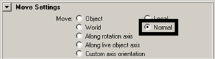
It is also possible to set the Move Tool to move objects and components based on other coordinate systems, such as object space and local space.
In addition, you can also move a polygon component in relation to its surrounding mesh. For example, you can select and move a vertex in a direction that is perpendicular or normal to its surrounding surface mesh. This is a useful technique for correcting any protruding vertices on the mesh.
To move a vertex on the mesh in a direction normal to the mesh
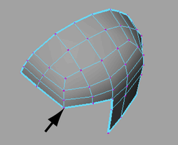
The vertex highlights and the Move manipulator appears to indicate the three directions of movement that are possible in this mode.
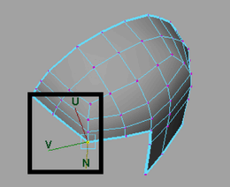
The U and V handles slide the vertex in relation to its associated edges, while the N handle moves the vertex either away or towards the mesh depending on the direction you move your mouse.
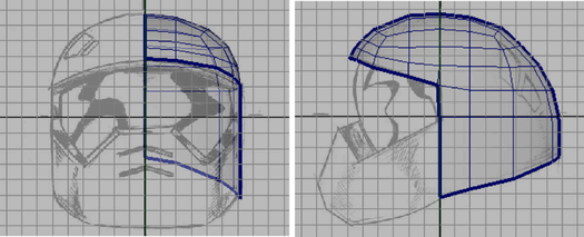
If you examine your model in the perspective view your helmet mesh should now match the reference sketches as they appear in both the front and side image planes (see image below). The mesh should also have a relatively uniform distribution of polygon faces on the mesh and the edge loops should flow smoothly.