Mesh > Sculpt Geometry Tool


Use this tool to sculpt NURBS, polygons, and subdivision surfaces. See How Artisan brush tools work in the Artisan guide.

Related topics

Mesh > Sculpt Geometry Tool >

Lets you specify the settings for the Sculpt Geometry Tool in the Tool Settings editor. There are attributes unique to the Sculpt Geometry Tool in the Sculpt Parameters sections. These unique attributes are described below.

For descriptions of all other attributes in all other sections of the Sculpt Geometry Tool, see Artisan Tool Settings in the Artisan guide.

Sculpt Parameters

These are descriptions of the attributes in the Sculpt Parameters section.

Operation

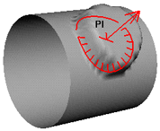
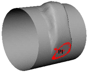
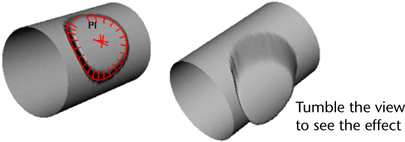
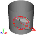
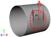
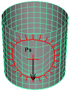
Select Push, Pull, Smooth, Relax or Erase. A letter appears within the brush stamp to reflect the operation: Ps (Push), Pl (Pull), Sm (Smooth), Re (Relax) or E (Erase).

To remove the letters from the brush stamp, open the Sculpt Surface Tool Settings window, click the Display section, and turn off Draw Brush Feedback.

When the Operation is set to Smooth, the Max Displacement and Reference Vector (X, Y, Z) options are respected. That is, the smoothing will be constrained based on what Reference Vector option is set and limited by the Max Displacement value.

TipTo select a brush operation from a marking menu, press your keyboard’s u key while dragging the mouse.
Auto smooth

When Auto Smooth is turned on, the surface is automatically smoothed for every brush stroke when using either the Push or Pull sculpting operations. The amount of smoothing is based on the Smooth Strength value. The Auto Smooth option is only available when either the Push or Pull sculpting operations are selected.

Smooth strength

Specifies the amount of smoothing the Sculpt Surface Tool applies to the surface for each Push, Pull, or Smooth stroke you perform. The Smooth Strength value ranges from 1 to 10. The higher the Smooth Strength value entered, the more smoothing takes place for each brush stroke.

Reference vector

In the Sculpt Parameters section, select the Reference Vector. The Reference Vector controls the direction the vertices move when you push or pull. The brush arrow represents the reference vector.

Normal

The vertices move in the direction of the surface normal.

First normal

The vertices move in the direction established by the surface normal at the beginning of the stroke.

View

The vertices move parallel to the camera view direction.

X Axis

The vertices move in the direction of the X axis only. They do not move along the Y or Z axis.

Y Axis

The vertices move in the direction of the Y axis only. They do not move along the X or Z axis.

Z Axis

The vertices move in the direction of the Z axis only. They do not move along the X or Y axis.

U

U moves CVs in the direction of the U isoparm when sculpting NURBS surfaces.

V

V moves CVs in the direction of the V isoparm when sculpting NURBS surfaces.

TipTo avoid overlapping isoparms when you sculpt along the U or V isoparms of NURBS surfaces, use a softer brush shape and keep the displacement small.
Max displacement

Type the maximum possible depth or height of the brush stroke, or use the slider to select it. (The actual displacement of the brush stroke is based on how hard you press with the stylus and on the Opacity value.)

Seam/Pole tolerance

Set how close the vertices must be along an edge, and how close the edges on the same surface must be to each other before they are detected as common. This is most commonly used to detect poles on surfaces like spheres.

Flood

Applies the Operation to all selected control vertices.