Learning Resources > Tutorials > Getting Started with Maya > Rendering > Lesson 3: Lights, shadows,
and cameras >
Creating additional cameras
in a scene
Elsewhere in this book, you’ve used the default perspective camera to examine and render your modeling and animation work in progress. In some situations, it is convenient to create and use additional cameras.
For example, you might want to render the scene from two different camera views to compare the results. Alternatively, you might want to use the default camera for interactive modeling and animation and the second camera strictly for rendering the scene. In the next steps, you create an additional camera and manipulate its view of the scene.
To create a second camera for the scene
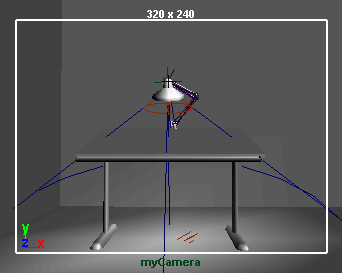
Even though you’ve created a new camera, you are still looking at the scene through the default perspective camera named persp. You will view the scene through myCamera after you position it in the next step. If you were to view the scene through myCamera now, you would see a disorienting view of the back wall and floor. The camera’s icon points in the direction of the camera’s view.
The scene’s default persp camera has no icon. An icon is displayed only for a camera you create.
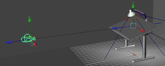
With a camera selected, the Show Manipulator Tool provides the same two manipulators that you used to position the spotlight: eye point and look-at point. The look-at point sets where the camera aims. The eye point sets the position of the camera.
You can select the current camera by selecting View > Select Camera.
If your camera view is not similar to the above illustration, select tableGroup in the Outliner (Window > Outliner) and select View > Frame Selection from the panel menu. This centers the view of myCamera on the table.
The dolly, track, and tumble movements work the same for myCamera as they do for the default persp camera.
You can return to the view of the persp camera by selecting Panels > Perspective > persp.
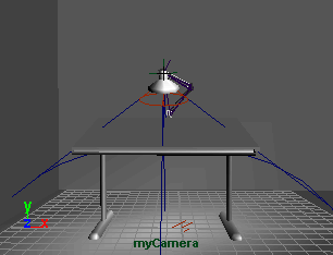
By enabling the Overscan, the view displays more of the region outside the area that will be rendered.
By displaying a small part of the scene that lies outside the rendered area, you can plan future camera movement more easily, especially if the scene has objects that move in and out of view.