Creates one or more ruled surface by pulling a group of surface curves at an angle to the normal of the original surface(s), or by pulling any number of curves at an angle to a pull vector. The curves can be continuous or disjoint.
The Multi-Surface Draft tool uses surface edges, curves on surface, isoparametric curves, and in Draft mode, even free curves, to create a ruled surface (or group of surfaces) that extends away at an angle to the original surface (or curve).
You can build a single surface across all of the input curves, provided that they are tangent continuous.
 and Surfaces > Draft Surfaces > Draft/Flange
  .
.
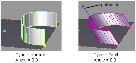
Normal – Creates a surface that extends away at a given angle from the normal of the underlying surface(s). By default, the new surface is normal to the underlying surface(s).
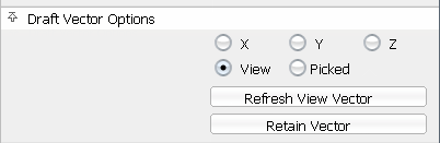
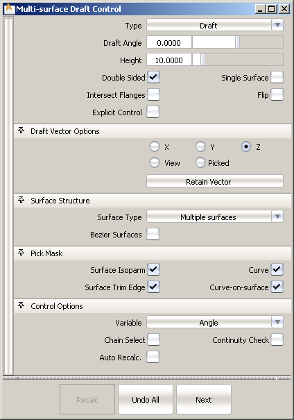
Draft – Creates a surface that extends away at a given angle from a specified pull direction vector. By default, the surface is parallel to the pull vector.
In this mode, you can individually select, or box-select, any combination of curves (even free curves), whether they are disjoint (non-touching), G0 (position continuous) or G1 (tangent continuous).
Turn on this option to handle corner conditions when two flange or draft surfaces meet. The surfaces will be trimmed or extended so that they join properly at corners.

Left: draft angle = 35; surfaces are extended, intersected and trimmed. Right: draft angle = -35; surfaces are intersected then trimmed.
If Surface Type is set to Multiple surfaces, this value specifies the maximum number of spans for each draft surface. If Surface Type is set to Single surface, it specifies the maximum number of spans for each piece of the original surfaces.
This option only appears if Explicit Control is checked, and Bézier Surfaces is not checked.
These options let you choose what types of curves are selectable as input. This is especially useful when using box selection.
Gives you the ability to interactively modify the angle or height of the new surface by clicking and dragging the manipulators.
Angle – Allows you to adjust the angle of the surface. You can create any number of manipulators by clicking along the input curves, and then adjust the angle individually at those points.
Height – Allows you to adjust the height of the surface. You can create any number of manipulators by clicking along the input curves, and then adjust the height individually at those points.
Using the manipulators to control angle and height
The Variable option in the control window specifies which of the parameters (Angle or Height can be varied when interacting with the manipulators in the modeling windows. The other parameter is held constant.
Each manipulator consists of two handles — the curve slider and the value handle — only one of which can be active at a given time. The active handle is shown in light blue. The curve slider, a "ball" sliding along the input curve, indicates the position on the curve where the value applies. The value handle, a straight “spike”, controls the value of the parameter (angle or height) at this point.
The value of the active handle is shown on the prompt line.

For all of the following operations, use the  , unless stated otherwise.
. Alternatively, activate the slider ball and type in the position (in the range from 0 to 1) along the curve.
 -right click it.
If a single manipulator is used, the parameter is constant, and its value can also be adjusted in the option box. As soon as another manipulator is added, the value in the option box is grayed out.


 to create a vector object.