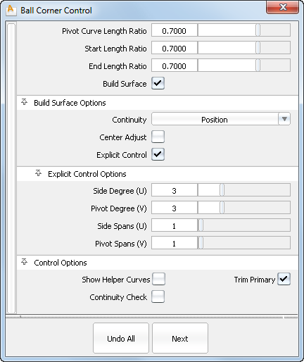
Creates a ball corner surface between three fillets and a primary surface.
See Create ball corner surfaces for detailed workflow.

Specifies the ratio between the chord length of the pivot curve (top of the ball corner) and the chord length of the opposite edge on the ball corner. A ratio of 1.0 means both chord lengths are equal.
Both end points of the pivot curve are moved the same distance from the apex (intersection point between the two top fillets). Use this control to make the pivot curve symmetric.
Modifies the length of the first half of the pivot curve only, in the manner described for Pivot Curve Length Ratio.
Modifies the length of the last half of the pivot curve only, in the manner described for Pivot Curve Length Ratio.
If checked, any changes in any field in the option window leads to an automatic update of the ball corner surface. This is the default.
If this is not checked, the ball corner surface, if any, is deleted, and only the hole is constructed.
Controls the level of continuity between the ball corner and four input surfaces. The possible choices are Position, Tangent, and Curvature. The default is Position. .
If this option is checked, you can use the Center Height slider to adjust the center (peak) of the ball corner.
Moves the center point of the ball corner (in parametric uv-space) along the surface normal by the specified distance (in current linear units).
This slider is designed for minute adjustments to the center point.
Turn on this option to open the Explicit Control Options section that allows you to explicitly specify the degree and number of spans of the ball corner in both the U and V direction.
Maximum number of spans that can be added to the ball corner in any direction while attempting to achieve the requested level of continuity (tangent or curvature).
This option is only available if Explicit Control is turned off, and Continuity is set to Tangent or Curvature.
Specifies the degree of the ball corner in the U direction. The default is 3.
Specifies the degree of the ball corner in the V direction. The default is 3.
Specifies the number of spans for the ball corner in the U direction. The default is 1.
Specifies the number of spans for the ball corner in the V direction. The default is 1.
If this option is checked, special helper curves used to build the ball corner are displayed.
If this box is checked, continuity locators appear along the boundaries between the ball corner surface and input surfaces, indicating the level of continuity.
P – Positional continuity
T – Tangent continuity
C – Curvature continuity
Green means “achieved”; yellow means “not achieved”.
if checked, the primary surface is trimmed to the intersection with the transitional surfaces (that is, to the pivot curve of the ball corner).