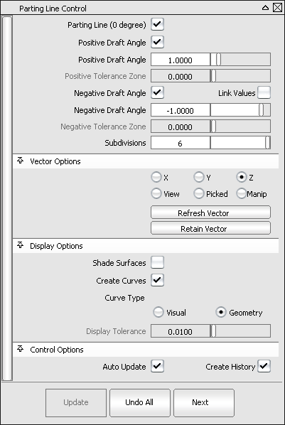
The tool has undergone some important improvements in this release. Below is the new control window followed by a list of the
changes.
- You now have the ability to evaluate in-draft and out-of-draft regions along both directions of the pull vector. This is useful
since a mold often separates in both directions. In the control window, you can specify both a and a (or turn on so that the positive and negative values mirror each other).
- let you specify the pull vector direction. The options are similar to other modeling tools, including , , ,, , and options. The latter is automatically selected when using the manipulator. The default direction is along the Z axis (as before).
The,, and fields have been removed.
- When is turned on, checking on the option displays the zero-degree line (where the mold separates) in addition to the positive and/or negative draft lines.
- is a new option that lets you shade the regions with different colors, just as with diagnostic shading.
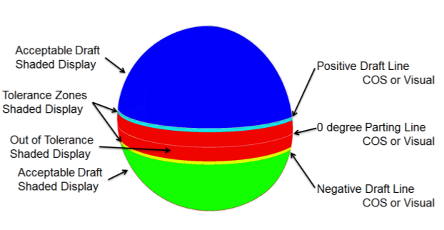
- When is on, sliders are enabled below the positive and negative values to specify positive and negative angle tolerance zones between the in-draft and out-of-draft regions. Up to five colors
can be used to show the different regions, as shown below.
- The old slider has been renamed and only becomes available when is checked on, to emphasize the fact that it applies to the display of visual curves only.
Selection workflow
Surfaces can now be selected, box-selected or de-selected (by clicking on them a second time) after entering the tool.
The box selection obeys the mouse button settings in . However, box selection cannot be used to select meshes, or input vectors. Those still require single mouse clicks.
Note When box selecting, be careful not to mouse down on a mesh, vector or surface, as the tool does single picking on mouse down.
Changes to Draft Angle diagnostic shading
The diagnostic shading options in the Control Panel now include additional fields for a negative draft angle and negative tolerance
zone angle when is checked on.
Performance enhancement
If is turned on (in ) curves-on-surface created by the tool temporarily become visual curves during the interactive updates, in order to provide faster redraw. This does not happen
if the curves-on-surface have locators on them, are used in trimming, or if the transformation requires the tessellation to
be recomputed (for example, in ).
NoteThis also applies to curves-on-surface created with the and tools.


