Lets you view a cross section of surfaces or meshes by dragging a plane through the model.  
         
         This tool produces cross-sections in an arbitrary orientation by using a series of parallel planes with a distance between
            them specified by . 
         
         Unlike the  cross sections available from Windows > Editors > Cross Section Editor, dynamic sections update interactively on the geometry as you transform the reference plane. 
         
          
            Dynamic Sections Control


               Sections
               
 -   
 
                  - 
                     
 
                        The number of cross-section lines to create. 


                   -   
 
                  - 
                     
 
                        The distance between cross-section lines (when  is  and  is greater than 1). 


                   -   
 
                  - 
                     
 
                        Controls the size of the curvature combs on the cross-section lines. 


                   -   
 
                  - 
                     
 
                        Controls the number of equally-spaced quills that appear on the curvature combs. The default is 50. 


                   -   
 
                  - 
                     
 
                        This flag determines whether the sections will remain after exiting the tool. 
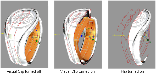


               Visual Clip
               
 
               These options let you visually clip the wireframe and shaded model, leaving the sections visible. 
               
 -   
 
                  - 
                     
 
                        Check this option to display only the part of the model with the sections (on one side of the sectioning plane). 


                   -   
 
                  - 
                     
 
                        Check this option to display only the part of the model that does not have sections. The sections on the invisible part are
                           still displayed. 


                   -   
 
                  - 
                     
 
                         This option is only available if  is turned on. 
                        
 
                        When checked on, a second clipping plane appears, and the display of surfaces/meshes is clipped to the location and direction
                           of that second plane as well, leaving only the part of the model between the two planes visible. 
                        
 
                        The  slider specifies the offset distance of the second clipping plane from the first. 


                  Section Origin
                  
 -   
 
                     - 
                        
 
                           These fields specify the position (X,Y,Z) of the sectioning plane’s origin. They let you cut a section at a precise location
                              along one of the main world axes (for example x = 100). 


                      -   
 
                     - 
                        
 
                           These fields specify the rotation angle of the sectioning plane around the world X,Y,Z axes. 
                           
 
                           Click the button in the view window to reset all rotations to 0.