In Alias 13.0, the way in which Curvature Continuity is evaluated was changed. This section describes the changes, the reasoning behind the changes and also explains how you can interpret the results during the modeling process.
For users of previous versions of Alias, this new method can appear significantly different from the way curvature continuity was evaluated in the past.
The intention of this section is to assure you that the change is not something that you need to worry about while evaluating the quality of your models, and to help you better interpret the results of curvature continuity evaluation at surface boundaries.
Starting with version 13.0, Alias uses a relative check for curvature continuity evaluation instead of the absolute difference check that was used in prior versions.
V13 – The Relative Curvature Deviation Method
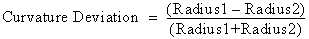
(2)
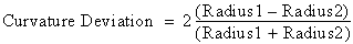
There are other software packages that use a similar relative curvature continuity check but have a factor of 2 built into their deviation calculation. In other words, their method of calculating can be expressed as:
The curvature continuity calculation has been modified for better control of surface transitions and accuracy. Specifically, the relative check was implemented in V13.0 for the following reasons:
The curvature continuity evaluation is much stricter now with the relative curvature continuity checking.
For example, in V12.0, the third curvature CV could be moved freely, yet the curvature evaluation might have stayed within tolerance. For example, as long as R1 and R2 were larger than 10 centimeters and 1/R1 – 1/R2 was less than the tolerance of 0.1, changes could be made to the third curvature CV without breaking the curvature continuity.
In contrast, in V13.0 onward, curvature continuity checking is more sensitive and flags errors more strictly.
In V12.0, the curvature deviation would change as the model was scaled. Hence, curvature continuity could be achieved within tolerance simply by scaling up the model. This can be considered acceptable as curvature discontinuity between two surfaces becomes less visibly obvious if the radius values of the surfaces become larger.
In V13.0 (and later), the curvature deviation does not change by scaling the model to make it larger or smaller – until a point is reached when a surface is scaled such that the radius is large enough to be considered flat. Flat surfaces are an important consideration now with the new curvature continuity calculation. (See Flat surfaces.)
Curvature continuity evaluation indicates a transition between surfaces and the quality of the highlight flow across surface boundaries. It is not necessary to have the same radius value on both surface boundaries for an acceptable transition and aesthetic highlight. A small difference may cause a curvature deviation value larger than 0.1 (curvature tolerance) and result in a yellow or red locator when using the Surface continuity tool, yet the quality of the highlight may be good. The curvature locator is just one factor in judging curvature continuity. You need to judge the curvature deviation value, highlights, curvature combs on cross sections etc,. and these may satisfy the desired result even with a curvature locator indicating a failure.
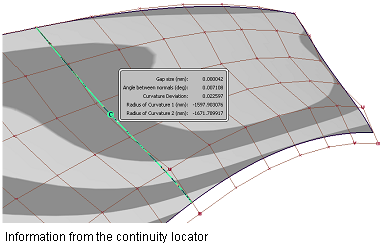
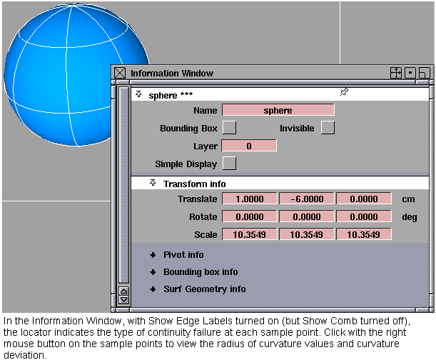
When Show Edge Labels is turned on (in the Surface continuity tool or Information Window), clicking with the right mouse button on the sample points of the locator shows you the radius of curvature values and the curvature deviation. The number of sample points can be increased by dragging the middle mouse button up or to the right, and decreased by dragging down or to the left.
The radius of curvature values along the boundary depend on the direction in which the curvature is measured. The direction used in Alias is perpendicular (90 degrees) to the common boundary between the surfaces.
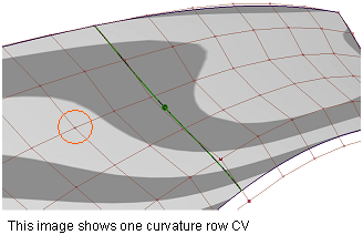
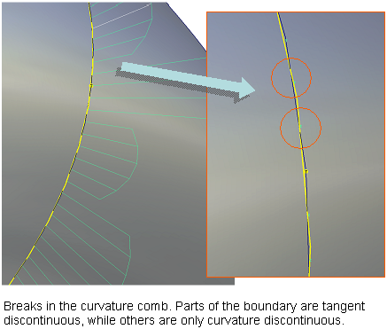
In the Surface continuity tool, or Information Window, turn on Show Comb to display the curvature comb. The curvature comb may appear broken as shown in the following image. This indicates that there is a change in the type of continuity failure, and is helpful when working with individual CVs.
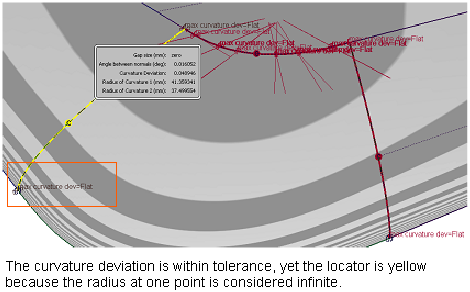
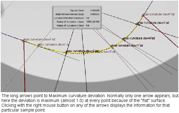
When a relative calculation for curvature continuity deviation is used, as one radius keeps increasing, the curvature deviation tends toward the value 1.0.
This is not necessarily a visual curvature problem, but it is necessary to inform you that the radius of curvature on one of the surfaces is approaching an infinitely high value. A purely flat surface is one which has an infinite radius of curvature; therefore this condition is flagged as FLAT. A radius larger than 100000 centimeters is considered infinite. The curvature evaluation shows a yellow locator labeled FLAT only if the radius is infinite on one surface across the common boundary, and not infinite on the other one. If both radii are infinite, then the curvature deviation tends toward zero and the curvature evaluation check passes.
Seeing such a failure condition (as indicated by the color of the continuity check locator) does not mean that there is a noticeable curvature break. It just means that there might be a potential problem and you should use other diagnostic tools, such as highlight lines (zebra stripes), curvature combs on sections, and so on, to decide if the result is acceptable.
This method of indicating a flat surface in the continuity check is not unique to Alias, but is common in many other engineering or CAD software packages.
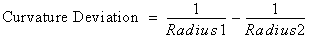
By contrast, the absolute (old) method of curvature deviation would often show that curvature continuity had been achieved in this case, even if the two surfaces had widely different curvatures at the join. To see this, substitute R1=10 and R2=1000 in formula (1). The result is 0.099, which is smaller than the default tolerance of 0.1.
Since curvature continuity is calculated differently in V13.0, its tolerance value (Continuity Curvature in the Construction Options) now has a different meaning.
In Alias, the tolerance is expressed as a number in the range of 0.0 to 1.0.
Other software packages may express the same value as a percentage. For example, a value of 0.1 in Alias corresponds to a value of 10% in other packages. B e aware of this to map Alias’s values relative to the values of the system under consideration.
You can set environment variable ALIAS_G2_INFINITY_TOL to any value that should be considered as an infinite radius (in centimeters).
Any radius greater than this value is considered infinite in determining flat surfaces during curvature continuity checks. Alias’ default value is 100000 centimeters.
If this value is increased, the word FLAT appears less frequently, but curvature deviation values such as 0.999 (as it’s nearing 1.0) appears instead.
If this value is decreased, more green curvature continuity locators appear, because both surfaces have a radius greater than this value, and the curvature continuity check indicates a pass.
Using and interpreting the results
Finally, here are some important points to keep in mind while using curvature continuity evaluation during the modeling process.