To save a DWG or DXF file
- Choose File > Export > Active As
 ❒.
❒.
or
- File > Save As
 ❒.
❒.
- From the menu, choose or .
You are presented with two options.
- Set the options as desired, and click .
Options
-
-
If this option is ON, the curves are exported, otherwise they are ignored.
-
-
If Split Surfaces at internal discontinuities is ON and a surface has G1 discontinuities, it will be divided at each G1 discontinuity
break.
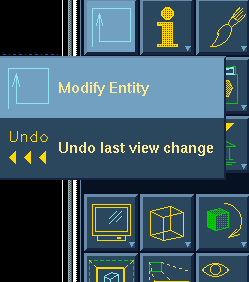
To open the History Access window
- Choose the menu item from the second section of the icon panel.
- You are prompted to select the entity for which you want information. Select the model on the workbench, and in the Access
window select the orphan node of the part.
Note
Before importing the new Alias model, the Orphan Node of the original model is selected (active) for the replace routine to be used.
Next, you will import the Alias wire file model which represents the changes that are required to be incorporated.
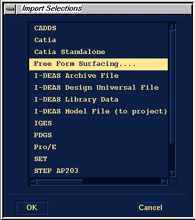
- Choose . From the File Import list, choose .
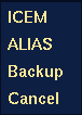
- A popup window displays.
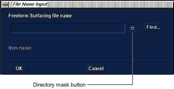
Choose . The File Name Input window appears.
Either:
- type the fully qualified path name of the file you want to import in the field.
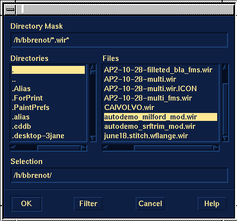
- select the directory mask button (labeled above) to use a file lister from which you can select the file you want to import:
- Choose .
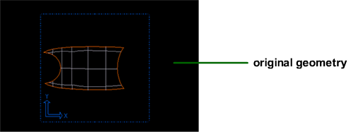
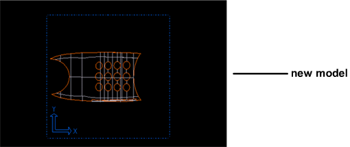
The I-DEAS List window displays the import progress and the new model is imported on top of the original geometry.
- Once the model has been imported, if necessary, position the stitched geometry where you want it in relation to the existing
part in I-DEAS Master Series.
- Ensure that the orphan node of the original model is still active, and then choose .
Note
You must be able to stitch together this surface geometry once it is in I-DEAS Master Series to ensure its status as either
a closed or open solid.
Note
For information on creating and confirming stitched geometry, see the Creating a Solid section.
- A popup menu is displayed. Choose .
You are prompted to select the geometry that will be used to replace the original feature.
- Once you select the feature, you are prompted whether or not you want to control the associativity of mapping the old and
new geometry.
If you choose , the screen splits into two areas. You are prompted to map the original geometry to the geometry of the newly imported model.
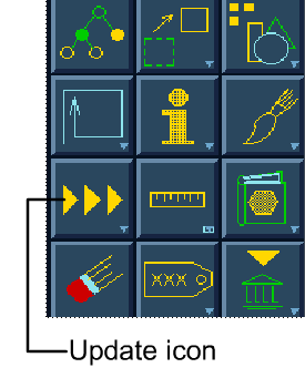
- When the mapping has been completed, click the icon from the second section of the icon panel.
The original feature is replaced by the imported geometry and a new feature exists with all the nodes acting upon the new
Orphan Node.