


How to create theoretical intersection curves (and feature curves approximations) that can later be used for surface development.
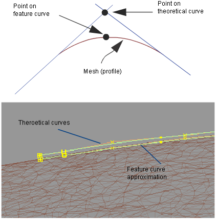
An input curve (as an approximation of the feature curve) and radius of influence must be provided to calculate the theoretical intersection curve. If you do not have such a curve, you can input a series of points along the feature to create an approximation to the feature curve.
The output consists of a theoretical curve, and, if using the point method, a feature curve approximation. The feature curve attempts to lie on the mesh as much as possible. The theoretical curve is drawn where both sides of the mesh (across the feature curve) would intersect if they were extended. The theoretical curve generally lies off the mesh.
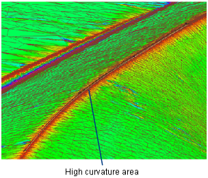
This will show you areas of high curvature where you may want to define theoretical intersection (or feature) curves.
To extract a theoretical curve from a mesh (curve method)
 ❒.
❒.
If the Show Curvature Evaluation option is on, the mesh is shaded with a curvature map.
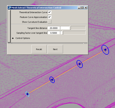
A blue radius manipulator appears at the start of the curve.
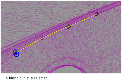
This creates a variable-radius cylinder and controls the shape of the resulting curve.
A degree 1 curve is produced: the theoretical intersection curve.
Tangent lines, drawn in yellow, show you where the tube intersects the mesh. They help you ensure that the radius is large enough to cover the entire transition region.
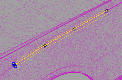
You can still add more radius manipulators or change others options in the option window then press Recalc to recompute.
To extract a theoretical curve and feature curve approximation from a mesh (point method)
❒.
If the Show Curvature Evaluation option was on, the mesh is shaded with a curvature map.
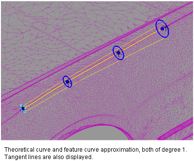
Each point appears with a blue radius manipulator and a cross in the middle. The cross can be selected to reposition the manipulator inside the feature.
An approximation feature curve is produced in addition to a theoretical intersection curve. Both curves have degree 1.
Tangent lines, drawn in yellow, show you where the tube intersects the mesh. They help you ensure that the radius is large enough to cover the entire transition region.
You can add more radius manipulators (by clicking on the feature curve) or change other options in the option window then press Recalc to recompute.