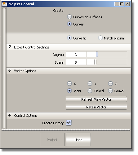
You can now define the projection vector from within the Project tool using the Vector Options, in the same way as with the Align or Draft tool. This way, you do not have to change the view, or create a vector construction object before entering the Project tool.
We have also converted the Project tool’s option window to a control window. This lets you:

The following vector options are available:
Specifies a projection vector along that axis.
Specifies a vector normal to the current view. The vector is not drawn in the view windows.
If the current view is changed, click Refresh View Vector to update the vector.
Lets you specify the name of an existing vector in the Picked Vector field, or pick the vector in the view.
The projection is done along the surface normals instead of using a single vector direction.
In addition, the following two buttons are provided:
This button only appears if View is selected. Click it to update the vector if the view has been modified
Click this button to create a vector construction object in the view windows.Otherwise, the tool uses the vector direction you specified, but you are not able to see and re-use the vector.
The default is View, so by default the tool behaves as before. If you select an existing vector, the Picked option is selected in the control window, and the name of the vector appears in the Picked Vector field.
Since the Normal vector option duplicates the functionality of the Project Normal tool, we have removed that tool from the Surface Edit tab in the tool palette.
Different versions of the Project tool can be created by setting the vector option and saving the tool on a shelf.
Creating curves-on-surface by projection
By default, the Create option is set to Curves-on-surface. The workflow below demonstrates the new flexibility of the tool.
To specify and change the projection vector from within the Project tool
The control window opens.
The surfaces turn pink.
The curve is projected along the View vector of the active window, by default. A curve-on-surface is created on the surface(s). This is the same behavior as before.
The curve-on-surface updates according to the new view vector in the Perspective window.
The curve-on-surface updates.
The name of the vector appears in the Picked Vector field. The curve-on-surface updates according to the picked projection vector.
The control window disappears.
The Project tool control window opens. You can modify the options and watch the curve-on-surface update. As always, this only works if the curve-on-surface was created with construction history.
Creating free curves by projection
When Create is set to Curves, additional options appear in the control window.
When this option is selected, the edit points from the original curves are projected on the surface(s), and the projected curves interpolate them, resulting in a similar number of spans. This behaves the same as in Alias 2010.
When this option is selected, a new fitting algorithm is used to fit a free curve to the projected curve-on-surface. This produces a curve that is generally closer to the surface, and with less spans than in Alias 2010. It also gives you explicit control on the degree and number of spans through the Degree and Spans sliders.
Lets you control the degree of the projected curve in Curve fit mode.
Lets you control the number of spans of the projected curve in Curve fit mode.

The workflow is the same as when creating curves-on-surface (see above). When the projected curve is first created, it has the same degree and number of spans as the input (original) curve.
If you are using the Curve fit method, you can modify the degree and number of spans of the projected curve through the control window. The projected curve and its maximum deviation locator update accordingly. The deviation locator shows the maximum distance between the projected curve and the surface.
Projecting curves in 3D trimming
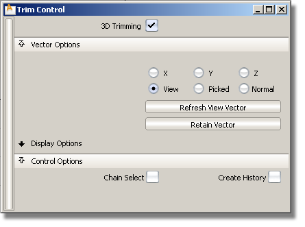
The vector options are also available from within the Surface Edit > Trim > Trim Surface and Surface Edit > Trim > Trim Convert tools when using the 3D Trimming option.

We removed the Project Normal checkbox since the Normal option is now found in the Vector Options section.
In the Trim Surface control window, the Projection History option has been renamed Create History and moved to the new Control Options section along with Chain Select.
The workflow for both tools remains the same as before, with the following exception: after selecting the trimming curve(s), the projection vector can be modified from the control window and the curves-on-surface will update. This can be done until you click the Keep, Discard, Divide (or Convert) button and trim the surfaces.