Applies motion path animation to any valid active objects.
Animation > Tools > Set Motion  lets you create several
different kinds of segments of animation.
For example, you can do the following:
When you use Set motion, up to four different types of animation are computed, depending on the current option settings:
Using Motion Path with Bank and Follow
![]()
When used with the default option settings, Set motion animates an object along a motion path with both Follow and Bank animation, using a combination of three types of animation. These defaults ensure that the assigned object rotates to continually point in the direction of the path curve throughout the motion. The object will also bank appropriately through areas of varying degrees of curvature if the Maximum Bank option is set to a value other than zero.
The following steps show how to create a motion path with Follow:
 to create a cone primitive.

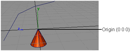
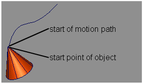
 ) and place the start of
the copied curve at the origin. Use this curve to help you set the
orientation of the object. This curve can be deleted later.
 ). See the side examples.
 . The system prompts:
Pick a curve to be used as a motion path.
Click directly on the curve that you want to assign as the motion path. It is assigned as a motion path for the active object.

 to view the animation.
Because Follow was toggled on, notice how the object rotates to follow the path curve and is continually pointing straight ahead throughout the entire frame sequence.
The Action Window displays action curves for the rotation of the object around all three axes.
These curves represent the necessary rotation of the object to maintain the original orientation to the path curve. You can edit any of these action curves to fine-tune the animation of the object.
The following example describes how to animate a snake slithering along a path.
Creating smooth and natural movement when using Flow
 to set the rotation pivot
to the tip of the snake’s head (the front of the object).
 on the object to orient the
snake so that it is pointing in the direction it will travel along
the motion path. It should be positioned so that it is aligned tangent
to the start of the curve.
Pick a curve to be used as a motion path
A series of messages appear on the prompt line, informing you of the animation’s progress.
 to view the animation.
If you don’t like the
generated animation, you can delete the clusters that were created
to animate the snake (ensure that the clusters are the only active
geometry and then choose Delete > Delete Active  .) Since all the flow animation
was on the clusters, the snake will no longer be animated and you
can start again. You may want to try increasing the Flow
Slices and/or the Maximum Bank values
to increase the amount of banking.
Animating the camera along a motion path
 to create a default window set.
 and click in the perspective
window that belongs to the camera you want to affect. This forces
the Up point of the camera to point
straight up above the camera eye.
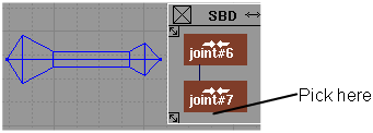
 and pick the eye DAG node
above the camera, as shown in the following diagram.
 to view the camera animation.
The animation may not be satisfactory because, although the camera
is moving, its lookat point is still fixed.
Animating the look at point of the camera

 to view the camera animation.
It will be easier to monitor the camera animation if you toggle
the camera visible. To do this, choose WindowDisplay > Toggles > Cameras
  . Ensure that the camera
is also toggled ON in the Optimization Options section
of the Animation > Show > Playback
  options window.
Motion path animation means that the objects move along a selected curve. The Motion Path option creates X, Y, and Z axis translation animation for each of the selected objects. If translation animation already exists for the active objects, it is replaced by the motion path animation.
The curve you want to
use as the motion path must exist before you invoke the function.
Curve-on-surface elements are not valid motion paths and must be converted
to world space curves using Curve Edit > Create > Duplicate Curve  .
.
To change the point on
the object that will travel along the curve, position the object
so that this point touches the origin, group the object using Edit > Group  , then use Animation > Tools > Set Motion
  on the grouped DAG node.
Ensures that the object assigned to the motion path rotates as necessary to maintain its original orientation to the path curve throughout the entire animation along the path. It points in the direction in which it is traveling (up or down, left or right) at all times. The Follow option animates the rotational parameters of the object in conjunction with the Bank option.
Applies a motion path curve to animate the Up DAG node of an animated camera or above its Eye DAG node. This option lets you control the camera animation, preventing the camera from twisting and turning upside down (as it would if the Up DAG node was not animated with respect to the Eye DAG node).
Camera Up creates X, Y, and Z translation animation for the Up DAG node of a camera. To create the animation on the Up DAG node of the camera, pick the DAG node above the Eye of the camera. If any translation animation already exists for the Up nodes, that animation is deleted.
Alternately, you could
choose View > Local Move Camera > Twist  to position the up point.
It is easier to position the up point of the camera if you display
the camera using WindowDisplay > Toggles > Cameras
  .
.
Before choosing Set motion, pick the Up DAG node for the camera you want to affect and move the Up point to the world space position that describes the sense of up for the eye point. Then choose Set motion. A NURBS curve is created that will be assigned as a motion path for the Up DAG node of the camera.
Banking In means the object will lean in towards the center of the curve that it travels along (like a motorcycle going around a corner).
Banking Out means the object will lean away from the center of the curve. Banking only occurs if Degree is set greater than 0.00.
For Follow and Bank animation to be computed, the active DAG node or at least one DAG node above it in the hierarchy must have positional animation.
 or another animation tool.
You can also have animation in the DAG node above the picked DAG node that is just rotational animation. In the DAG node below, this appears like a translation in an arc and Follow and Bank animation can then be computed.
 to orient the object and Transform > Local > Set Pivot
  to position the rotation
pivot of the object as the point on the object about which the Bank animation
is to occur.
The maximum allowable degree of banking. If set to 0.00, the object will not bank even if the Bank option is toggled on. The object will bank the amount specified by the Maximum Bank option when it is at the point on the curve with the highest curvature. It will bank a proportional number of degrees as the curvature changes. (It will not bank at all where the curvature is a straight line.)
Determines whether the animation is applied to the entire frame range of the animation (All) or only to the frame range specified by the current Start and End Frame values in this option window.
Defines the start and end frame values for the animation in relation to the entire animation. These settings only apply when Range is set to Option Window.
Used by the Follow and Bank options to determine how often to sample the positional animation when computing rotational animation. A keyframe is created for every Sample By frame.
This option is also used by the Camera Up option to determine how often to sample the Eye DAG node’s animation of a camera. The motion path curve that is created for the camera will have one CV for each sample of the eye DAG node’s animation.
Be careful to choose Start, End, and Sample By values that have a sufficient number of sample points along the length of the motion path to avoid sampling errors. As a general rule of thumb, you will encounter sampling errors if the change in tangency between any two adjacent sample points is greater than or equal to 90 degrees.
Sampling error can be remedied by increasing the number of samples taken, either by increasing the frame range or decreasing the Sample By value.
For example, animate an object using a circle primitive as the motion path, with Start at 0.0, End at 4.0, and Sample By at 1.0. The total sample points is 5. Since all of these sample points are 90 degrees apart, there are several chances for sample error to creep in and flip the animated object when you play back the animation.
When you toggle Flow ON (indicated by a check mark), Flow animation is applied to the geometry below each of the picked DAG nodes.
When you toggle Flow ON, the Set Motion Options window expands to display the following slider:

This is used by the Flow option to determine the number of slices, or clusters, that the object should be divided into for flowing.
Each cluster is animated independently. Unnecessary slices can be expensive in terms of processing speed. As a rule, the more CVs there are lengthwise on the object (from front to back as it travels along the path), the more slices you need. For a simple object such as a cylinder, for example, a few slices is sufficient.