In the previous lesson, you added layers to the Composite map while in Normal mode. In this mode, no blending between layers takes place: Visibility is determined solely by each layer’s alpha channel.
With the blending modes, you can produce interesting composite effects by choosing how pixels in the top layer interact with those underneath. In this lesson, you will use two blending techniques to add more layers to the composite map.
Add dirt to the bottom of the door with Multiply blending:
 (Add A New Layer).
3ds Max Design opens a file dialog.
On the file dialog, choose dirt-bottom.jpg, and then click Open.
This file shows dirt at the bottom of the door.
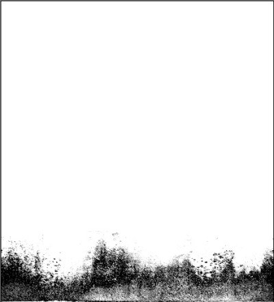
Bitmap used in the first blend operation
This file is a .jpg image that has no alpha channel. It completely obscures all layers beneath it.
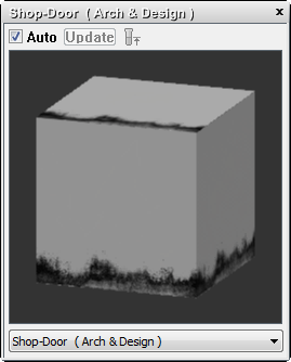
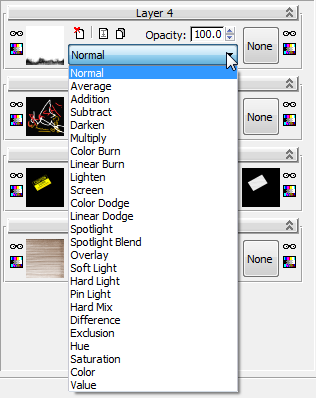
In addition to Normal mode, which we have been using so far, there are a variety of other methods for blending layers.
The options resemble those available in such paint programs as PhotoShop and Combustion. Refer to the 3ds Max Design Help for a description of what each blending option does.
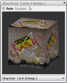
First blend operation using Multiply
This option multiplies the color value of all layers in the composite. The non-white color channels have a value of less than 1.0, so the multiplication tends to produce darker colors, a condition you will now correct.

The reduced opacity of the top layer results in a lighter overlay of grime.
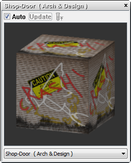
Add dirt to the top of the door with Linear Burn blending:
 (Add A New Layer).
3ds Max Design opens a file dialog.
On the file dialog, choose dirt-top.jpg, and then click Open.
This file shows dirt at the top of the door.
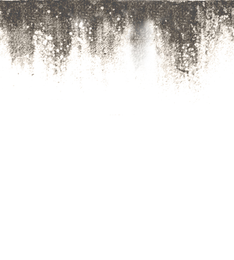
Bitmap used in the second blend operation
This file is also a .jpg image that completely obscures all layers beneath it.
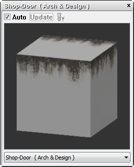
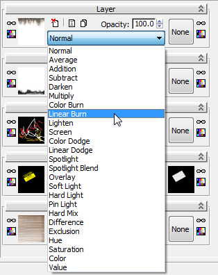
Linear Burn blending combines the new dirt map with underlying layers.
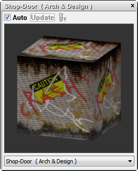
Second blend operation using Linear Burn
Linear Burn combines the color of pixels in the top layer with colors from the underlying layers. The darker the Layer 5 color, the greater the effect: As a result, the default blending is too dark.

Now the dirt at the top of the door, like the dirt at the bottom, blends well with the other textures.
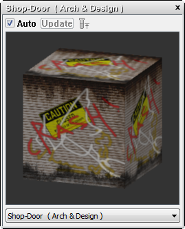
Add bump information to the composite:
 (Render Production).
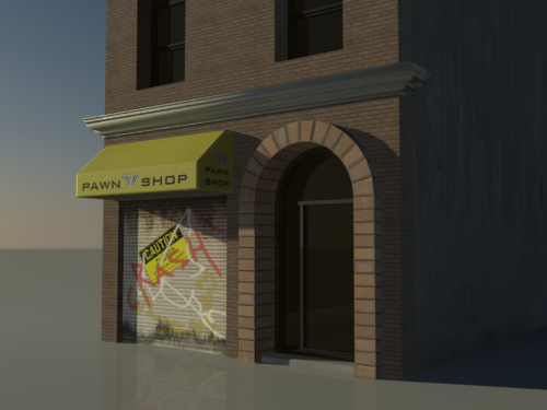
The shutter shows good detail, but in a rendering with shadows, its corrugated surface lacks depth. You will correct this by adding bump information from the shutters.jpg map.
 (Clone Rendered Frame Window).
 (Zoom Extents) to display
the entire material tree, and press L to arrange
the layout.
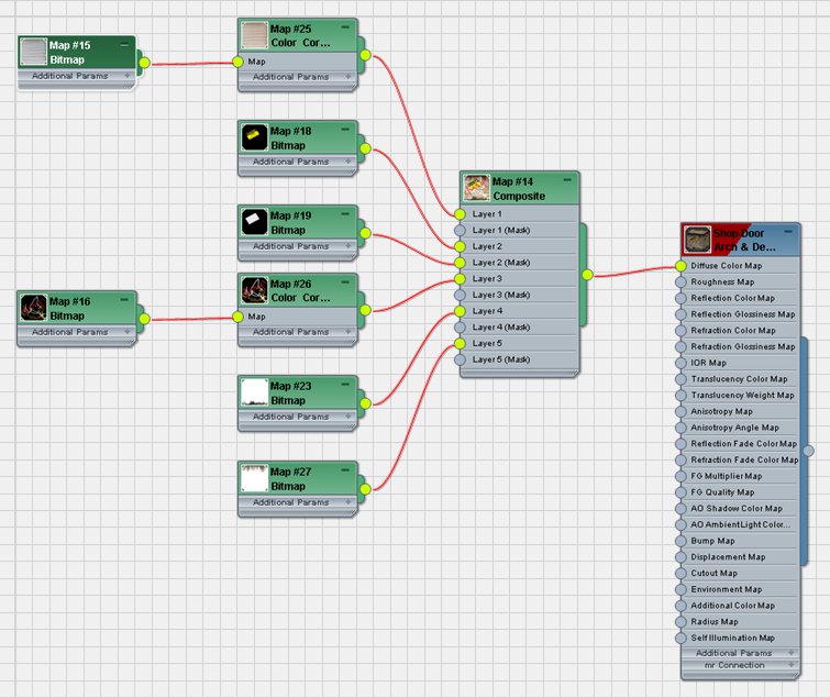
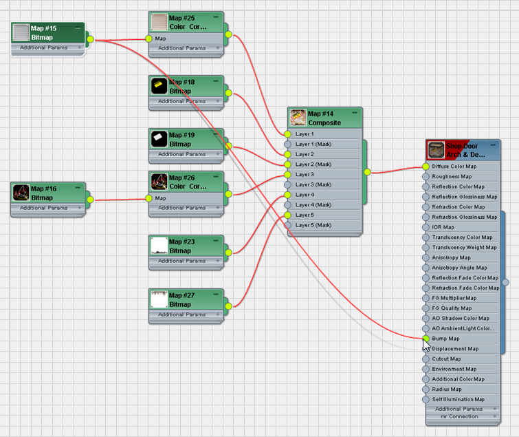

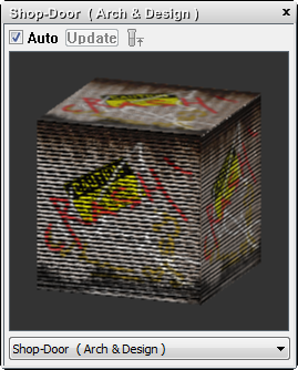
The effect in the preview is rather exaggerated.
 Render the Camera01 viewport
again and compare the result with the cloned rendered frame.
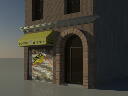
The fully composited shutter door, rendered with bump mapping
The shutter has lost its flat look and appears more three dimensional.
If you like, you can  open composite_completed.max and
compare your work with a completed scene file of this tutorial.
 Preferences
  General panel
  Texture Coordinates group and turn the option
back on.
In this tutorial, you learned how to create a composite map consisting of multiple layers of images. You used alpha channel information and a mask to control image transparency, then you used blending modes as an alternate way to specify how layers are composited.