


In this lesson, you will use a variety of freeform tools to create a ridge of irregular spikes for the Viking helmet.
 open helmet_04.max.
 select the helmet, and make sure the
  Modify panel is active.
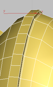
Remove the middle seam from the helmet ridge:
 Polygon Modeling panel, activate
  (Edge).
 (Loop Mode) to turn it on.
You will use this tool to remove the edge loop in the middle of the helmet ridge.
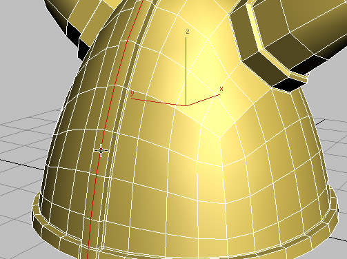
Click a vertical edge along the middle seam of the helmet ridge.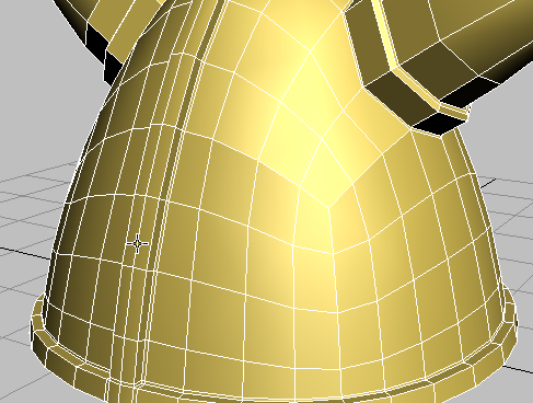
Loop mode selects the entire edge loop that forms the middle seam.
 (Remove).
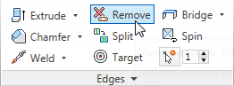
 (Vertex) sub-object level.
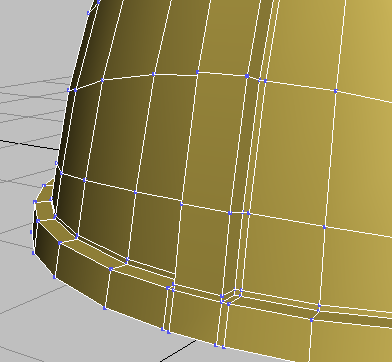
Notice that while the loop edges have been deleted, their vertices remain. You want to remove the vertices as well.
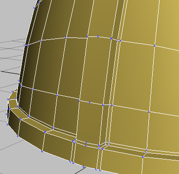
Unwanted vertices left over from edge removal
 Undo the Remove operation so that the loop redisplays.
(Edge) again, then on the Edges panel, Ctrl+click (Remove).
Undo the Remove operation so that the loop redisplays.
(Edge) again, then on the Edges panel, Ctrl+click (Remove).
Ctrl+Remove removes the vertices as well as the edges.
Both edges and vertices removed
Subdivide the ridge into rectangular faces:
Click and Ctrl+click to select two of the longer vertical edges on either side of the helmet ridge, as shown in the next illustration.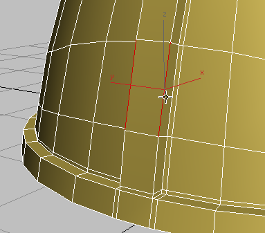
 (Connect).
 (OK).
(OK).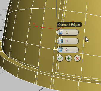
These values ensure you are connecting the edges just once, with no offset.
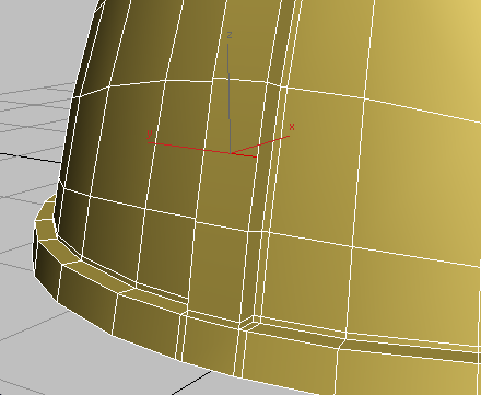 Select the next pair of edges above the ones you just connected, and click (Connect) to add horizontal edge to the ridge.
Create irregular spikes using the Freeform tools:
Polygon Modeling panel, activate  (Polygon).
Select the polygon at the base of the ridge.
(Polygon).
Select the polygon at the base of the ridge.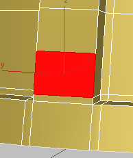
 (Branches).
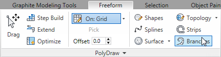
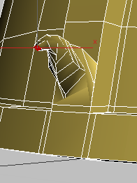
Helmet after first Branch extrusion
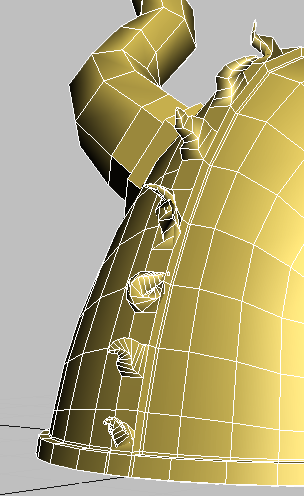
As you progress along the helmet, make sure you maintain an oblique view of the polygons. If you don’t like the shape of an extrusion, or you extrude the wrong polygon, press Ctrl+Z to undo the operation.
Graphic Modeling Tools tab again.
Polygon Modeling panel, click  (Polygon) again to turn it off, then press F4 to turn off edged faces.
 (Use NURMS) to turn it on.
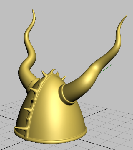
The helmet geometry is smoothed out and ready to accept materials.
Throughout this tutorial, you used a number of modeling tools on the Graphite Modeling Tools ribbon to create a Viking helmet. While these tools are also available from the Command panel, the ribbon gives you faster access, in context, as you need them.
This tutorial only scratched the surface of the many ways in which you can use the ribbon for editing mesh and polymesh objects. For a full description of the ribbon tools, consult the 3ds Max help. For more extensive exercises in polygon modeling, see Using Photos to Model Façades and Modeling an Airplane.