You set whether a joint behaves as a hinge, a drawer slide, or another type of joint by setting joint parameters for each object in the kinematic chain. Joints control the rotation and position of an object with respect to its parent.
Any object has a maximum of two joint-type rollouts: One rollout contains settings to control the object's position, and the other controls the object's rotation. There can be many different types of positional and rotational joints. Which joint parameters are available is determined by the type of IK solver assigned to an object. HI Solvers, for instance, are controlled with a preferred angle setting found in the Rotational Joint parameters. HD Solvers have additional parameters for spring back, precedence, and damping, not found in the HI Solver.
Any hierarchy of object or bone systems can have its joint limits defined. Select all the objects, and turn on their bone
or link display. Select the bone or link and open the Hierarchy panel  IK tab. Scroll down to the Sliding and Rotational Joints. There, you can activate axes and set their individual limits.
The most common joint types are Rotational and Sliding joints. Other common joint types are Path and Surface joints. Each joint type displays its own set of joint parameters.
Control rotation of objects using many of the standard rotation controllers. The parameters for rotational joints set an object's ability to rotate about a given axis.
For many IK structures, consider using an Euler XYZ controller. Quaternion-based controllers tend to freeze if an object is moved beyond rotational joint limits before turning on IK.
Control the position of objects using Surface constraint. The parameters control how the object travels along its assigned surface.
Control the positional motion of objects using Path constraint. The parameters for path joints control how far an object can travel along its assigned path.
The way the children behave toward one another is governed by the inheritance of the transforms down the chain. Setting joint limits on individual child objects can influence this inheritance. If three children in a row all have their rotational axes made inactive, they will not be able to rotate, and so a piece of the chain will appear stiff. Or if only one axis is made active as a sliding joint, the component can separate in space from the chain.
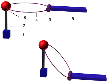
When you are using an object with a path constraint in an IK chain you might want the path to appear as if it is part of the IK chain. You achieve this effect by linking the object using the path constraint and the path to the same parent. The path object should have no children, and other objects in the IK chain should be linked to the object using the path constraint.

1. Base
2. Post
3. Cap
4. Ring
5. Holder
6. Handle

In the figure, the bead uses a path constraint to hold it to the ring. The IK chain from parent to child is Post->Cap->Bead->Handle. The ring is a child of the Cap but is not part of the IK chain.
Copying and Pasting Joint Parameters

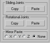
You can copy and paste at the bottom of the Object Parameters rollout in the Hierarchy panel to copy and paste a complete set of joint parameters from one object to another.
There are separate copy and paste functions for sliding joints and rotational joints. Each joint type saves copied parameters in separate clipboards.
You can also copy joint settings from a non-IK controller to an IK controller, but you can't copy from an IK controller to a non-IK controller.