The Camera Map modifier (object-space version) assigns planar mapping coordinates based on the current frame and the camera specified in the Camera Map modifier. This differs from the Camera Map (WSM) modifier, which updates the object's mapping coordinates at every frame.
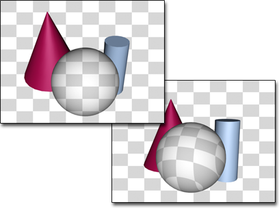
Left: The texture of an object with a camera map modifier matches the background when seen by the camera the modifier uses.
Right: When seen by a camera not used by camera map, the object’s texture is based on object geometry.
Blending an Object into the Background
In the Procedures section (following), you'll learn how to blend an object into the background with the Camera Map modifier. If the background uses the same image as the object's texture map, then the object blends with the background at the frame where the modifier is applied and a camera is specified. The object becomes visible if either the camera or object moves. In order to make the illusion work, you must assign the same map to the background that you assign to the object.
Because the accuracy of mapped objects depends partly on the complexity of the mesh, the "blend to background" effect works best when applied to an object with a relatively high density of triangular faces. The necessary density also depends on the distance of the object from the camera.
A simple box might look fine when it occupies only a small portion of the background, but up close the mapping will look distorted without adequate tessellation. Some experimentation is required to get an ideal mapping and still minimize the complexity of the geometry. (In general, for a box object that's filling a quarter of the screen, a tessellation of 4x4x4 works well.)
Use Camera Map (WSM) if you want to move the camera and maintain the match to the background.
Using the Plate Match/MAX R2.5 Rendering Filter
Prior to 3ds Max 3, the antialiasing affected only geometric edges, with the filtering of bitmaps being controlled in the Bitmap Map parameters
(pyramidal, summed area, or no filtering). Antialiasing filters affect every aspect of the object, filtering textures along
with geometric edges. While antialiasing provides superior results, it produces inconsistencies when rendering objects that
are supposed to match the environment background. This is because the antialiasing filters do not affect the background by
default. You can turn on background antialiasing in Customize  Preferences Rendering Background Antialiasing Filter Background. To correctly match an objects map to an unfiltered background image, you need to use the Plate Match/MAX
R2.5 filter so the texture is not affected by the antialiasing.
Preferences Rendering Background Antialiasing Filter Background. To correctly match an objects map to an unfiltered background image, you need to use the Plate Match/MAX
R2.5 filter so the texture is not affected by the antialiasing.
There are three ways you can render objects in 3ds Max to blend seamlessly into a background environment:
The Plate Match/MAX R2.5 antialiasing should be used whenever trying to match foreground objects with an unfiltered background or when trying to match the antialiasing qualities of the 3ds Max 2.5 renderer.
The following steps show how to apply the Camera Map modifier, and how to set up your scene.
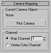
To apply the Camera Map modifier:
Be sure to use the Object-Space version of the Camera Map modifier.
To assign a background image to the Camera viewport:
Viewport Background.
3ds Max closes the dialog and displays the map in the viewport.
To assign a mapped material to the object:
 Material Editor, create a standard material to whose Diffuse component you've assigned the same bitmap as you assigned to
the background.
Material Editor, create a standard material to whose Diffuse component you've assigned the same bitmap as you assigned to
the background.
 (Show Map In Viewport).
 Select the object, and click
  (Assign Material To Selection).
The map on the object in the viewport matches the viewport background, but the shading makes the object visible. To make the object truly invisible, go to the next step.
To assign the background to the rendered background:
Environment.
If you don’t do this, you will be able to see the object in the rendering.
 Render the Camera viewport.
The mapped object is camouflaged against the background in the rendered scene.


 Modify panel