xView analyzes mesh models, flags various potential problems and errors, and displays the results in the viewports both graphically and as text. Tests include isolated and overlapping vertices, open edges, various UVW statistics, and more.
In addition, xView can convert its graphical display, such as highlighted vertices or edges, to a sub-object selection. And you can change the tolerance setting (distance) for relevant checks such as overlapping edges.
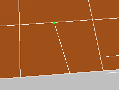
While a test is active, its name appears at the top or bottom of the active viewport; you determine the position by toggling the Display On Top command on the xView menu. You can open the xView menu by clicking this text.
The xView viewport display
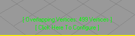
Next to the test name is a status message. If the test has been successful, the message indicates the results, such as “14 Vertices.” Otherwise, the message indicates a possible reason for the failure of the test, such as “No selection” (xView works only on selected objects) or “Unsupported object type” (xView works only on editable mesh and poly objects).
If the active test is configurable, the message “Click Here To Configure” appears on a second line after the test name. Typically
the configurable parameter is a Tolerance setting that determines the maximum distance for the test, such as between vertices.
To change the value, click the message or use the xView menu  Configure command.
Every command on the xView submenu is available from the Customize User Interface (CUI), so you can define keyboard shortcuts or a custom toolbar for frequently used functions. Also available in the CUI xView category are additional actions to cycle through the command list, toggle the viewport display, and more.
 Select the geometry to check; typically an Edit/Editable Mesh/Poly object. There is no need to access a sub-object level.
The test is performed immediately and the results, if any, display in the viewports as green-highlighted sub-objects: vertices, edges, or faces. At the same time, the name of the test and its numerical results display at the bottom or top of the viewport.

The xView functions work on editable/edit poly and mesh objects; most other object types (including primitives) are unsupported.
All of the modes relate to sub-objects: vertices, edges, and faces (whether geometry or UVW). However, you need not be at a sub-object level for a checker to display its results. The checker results appear at the object level and at all sub-object levels.

Toggles the viewport display of statistics for the entire scene, your current selection, or both.
Highlights the back side (see 2-Sided (Double Sided)) of each face in the selection. This is useful for checking for inadvertently flipped faces.
Highlights interpenetrating, coplanar faces. This should be avoided when possible to prevent rendering anomalies.
Technically, this test checks for at least one vertex of one face lying in the plane of another, so if only edges of two faces overlap, the test won’t find them. The Tolerance value specifies the distance from the vertex to the plane of the overlapping face.