


If your cabinet doors require flat, uniform surfaces, you can create them using the polygon modeling techniques covered so far in this tutorial. However, if you need to add more detail, you can use extrusions and bevel profiling as this lesson shows.
 open kitcab_2.max.
 Zoom in to the base cabinet and on the main toolbar, click to turn on
  (3D Snaps Toggle), then right-click the same button to display the Grid And Snap Settings dialog.
 close the dialog.
 Create panel, click
  (Geometry), then on the Object Type rollout, click Box.

First corner

Second corner
This is slightly less than the 0.75-inch board thickness we’ve used elsewhere in the cabinet. You will increase the door thickness later on when you use extrusion to add detail to the door surface.
 (3D Snaps Toggle) again to exit snap mode, then click
  (Select And Move).

Top view, with door slightly separated from cabinet
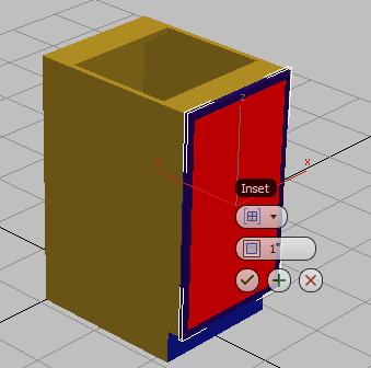
Use an extrusion to create a simple inset:
 Convert To Editable Poly.
Polygon Modeling panel, turn on
Convert To Editable Poly.
Polygon Modeling panel, turn on  (Polygon).
 select the front face of the door and on the ribbon Polygons panel, Shift+click
  (Inset).
3ds Max Design displays the caddy controls for the Inset tool.
 (OK).
(OK).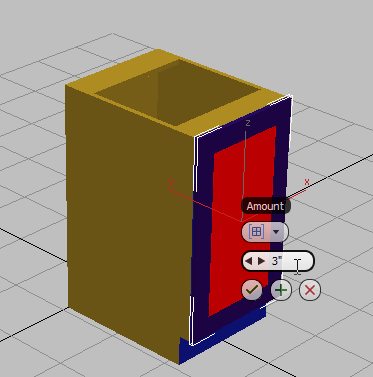 Click an empty area of the viewport to deselect all polygons, then click and Ctrl+click to select the polygons that surround the inset. On the ribbon Polygon panel, Shift+click
  (Extrude).
(OK).
(Extrude).
(OK).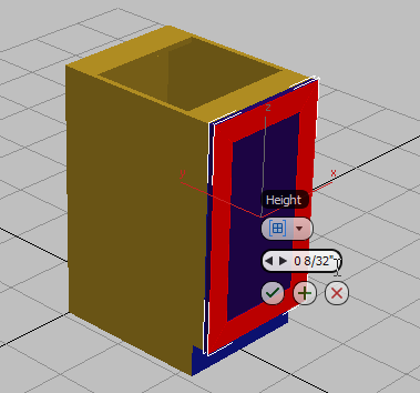
This creates a simple door with a center panel that is recessed by one quarter inch.
Polygon Modeling panel, click  (Edge).
Modify Selection panel, click
(Edge).
Modify Selection panel, click  (Loop Mode).
Click one of the edges that surround the inset panel.
(Loop Mode).
Click one of the edges that surround the inset panel.
3ds Max Design selects a loop around the perimeter of the panel inset.
 Edges panel, Shift+click
  (Chamfer).
 (OK).
(OK).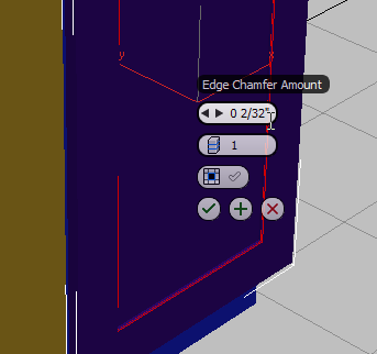
The inside edge of the raised panel now has a slight bevel to it.
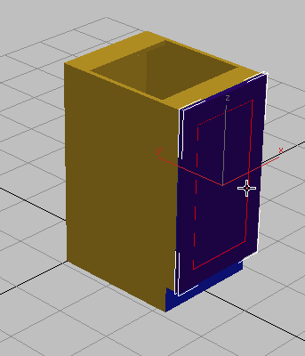
Select the outside edge of the door and click (Chamfer) to bevel the edge of the cabinet door. (You don’t need to Shift+click this time: The Chamfer tool will use the same value as the last time you used it.)
A combination of extrusion and chamfering is an effective way to produce a straightforward door. If you prefer to add even more detail, you can do so by means of a beveled profile.
Use bevel profiling to add detail:
In this procedure, you will backtrack and create an entirely new cabinet door using the Bevel Profile modifier and two 2D splines.
Polygon Modeling panel, turn off  (Edge) to exit the Edge sub-object level, then in the viewport, select the cabinet door you created in this lesson and press Delete.
zoom in on the lower cabinet.
Create panel, click
(Edge) to exit the Edge sub-object level, then in the viewport, select the cabinet door you created in this lesson and press Delete.
zoom in on the lower cabinet.
Create panel, click  (Shapes), then on the Object Type rollout, click Rectangle.
(3D Snaps Toggle).
(Shapes), then on the Object Type rollout, click Rectangle.
(3D Snaps Toggle).

You will use this rectangle as one of the two splines you’ll need to create the bevel profile. This spline will define the bevel area.
(3D Snaps Toggle).
 Modify panel, and on the Parameters rollout, set Length to 29 7/8 and Width to 17 7/8.
You now need to add a second spline, one that will define the shape of the bevel itself. You can draw the spline yourself, or use the line tool to trace over images of existing molding profiles, as shown in the next illustration.
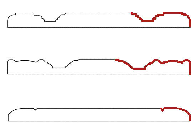
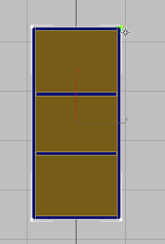
Cross section of sample cabinet door panels, with spline (red) traced over a portion of their profiles
Your kitcab_2.max scene file already contains three splines, ready for you to use.
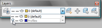
The three splines appear at floor level, off to the right of the cabinets.

 zoom out until the profile splines are visible.
 Close the Layers toolbar.
Modify panel Modifier List, choose Bevel Profile.
Close the Layers toolbar.
Modify panel Modifier List, choose Bevel Profile.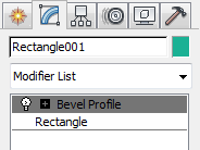

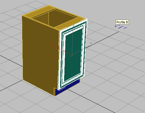
Cabinet (left) with spline profiles (right)
Create a bevelled door for the upper cabinet:
zoom in on the upper cabinet.
Create panel, click (Shapes), then on the Object Type rollout, click Rectangle.
(3D Snaps Toggle).
 (3D Snaps Toggle).
 pan down so you can see all of the upper cabinet.
Modify panel. On the Parameters rollout, set Length to 38 7/8 and Width to 17 7/8.
pan down so you can see all of the upper cabinet.
Modify panel. On the Parameters rollout, set Length to 38 7/8 and Width to 17 7/8.
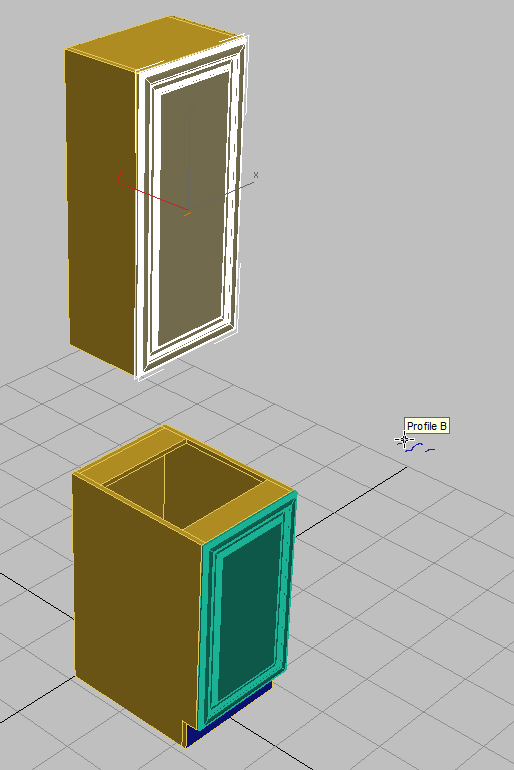
Cabinets with spline profile B applied to their doors
Next, you will adjust the pivot points so you will be able to open the doors properly.
 Hierarchy panel, and in the Adjust Pivot rollout Move/Rotate/Scale group, turn on Affect Pivot Only.
Move.
Hierarchy panel, and in the Adjust Pivot rollout Move/Rotate/Scale group, turn on Affect Pivot Only.
Move.
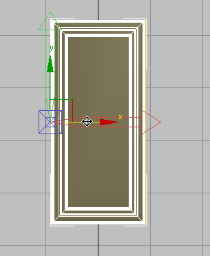
Pivot repositioned to the left side of the cabinet door
Rotate.

To this point, you have adjusted the pivots so the doors appear to move on hinges. Next, you’ll modify the cabinets for situations when you don’t need to open the doors.
Convert To Editable Poly.
select the lower cabinet. On the ribbon Geometry panel, click  (Attach), then click the lower door.
Set the material properties for the doors:
(Polygon).
Region-select all the polygons in the lower door.
(If the region chooses faces not part of the door, use Alt+click to remove those faces from the selection.)
 MatIDs, and on the Set ID dialog, change the Set ID field to 2. Press Enter.
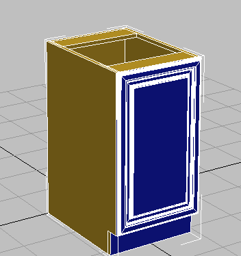
In the lessons that follow, you will learn how to produce other kitchen cabinets based on these two cabinets, the upper and the lower. The variant cabinets will have different dimensions or symmetry.