


The next step is to add a new part using 3ds Max Design.
Now you will construct a stirrup-like part to control the motion of the clamp.
 Create panel, click
  (Geometry). Choose Standard Primitives from the drop-down list, and on the Object Type rollout, click Box to turn it on.


New box in Perspective view
 Convert To Editable Poly.
Graphite Modeling Tools tab Polygon Modeling panel, click
Convert To Editable Poly.
Graphite Modeling Tools tab Polygon Modeling panel, click  (Vertex).
 region-select the vertices that define the top segment of the box (the second row of vertices from the top), and
  move them up along the Y axis so they are above the level of the upper blade.
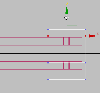 move them down along the Y axis so they are below the level of the lower blade.
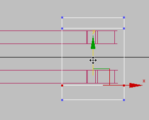 Polygon Modeling panel, click
  (Polygon).
 Orbit the Perspective viewport so you can see the inner side of the box.
 Click and Ctrl+click to select the two inner faces of the box that correspond to the upper and lower segments.
 Polygons panel, click
  (Extrude), then drag in a viewport to extrude these faces over the end of the blade clamp.
Add a pivot pin for the stirrup:
Create panel, click (Geometry). Select Standard Primitives from the drop-down list, then on the Object Type rollout, turn on Cylinder.
Move the pin horizontally and vertically so it straddles the “jaws” of the stirrup, and is inside the perforation of the
clamp blades.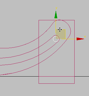
Top view

Front view
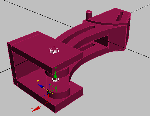
Perspective view