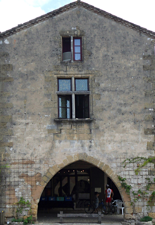
The second house front has a peaked roofline and an arched entry. We will concentrate on modeling these, as you already know how to model windows.
 open \modeling\facades\facade_modeling_04.max.
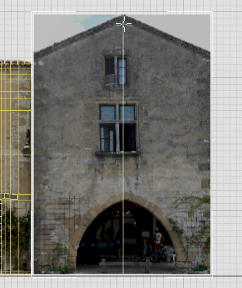
View the bitmap for the second house, and note its dimensions:
 View Image File. In
the View File dialog, navigate to the \sceneassets\images folder,
and highlight fac4.jpg.
View Image File. In
the View File dialog, navigate to the \sceneassets\images folder,
and highlight fac4.jpg.
In the lower-left corner of the View File dialog, a status line shows the dimensions of the image, which are 1200 x 1740 pixels.
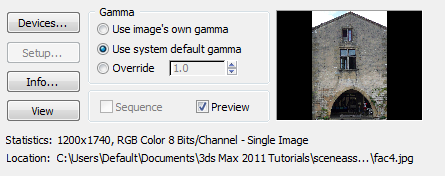
 Close the image window after
you have looked at the photo.
Close the image window after
you have looked at the photo.
Create the plane for the house:
 (Maximize Viewport Toggle)
to display a four-viewport layout.
(Maximize Viewport Toggle)
to display a four-viewport layout.
 Select Facade1, and then
click
Select Facade1, and then
click  (Zoom Extents Selected).
 Pan the viewport so Facade1
is at the left.
Pan the viewport so Facade1
is at the left. Create panel, click
  (Geometry), then on the
Object Type rollout, click Plane.
(Geometry), then on the
Object Type rollout, click Plane.
 Move the new plane so it
is level with Facade1, then move it to the right
so it is to the right of the previous house, with bit of distance
between them.
Move the new plane so it
is level with Facade1, then move it to the right
so it is to the right of the previous house, with bit of distance
between them.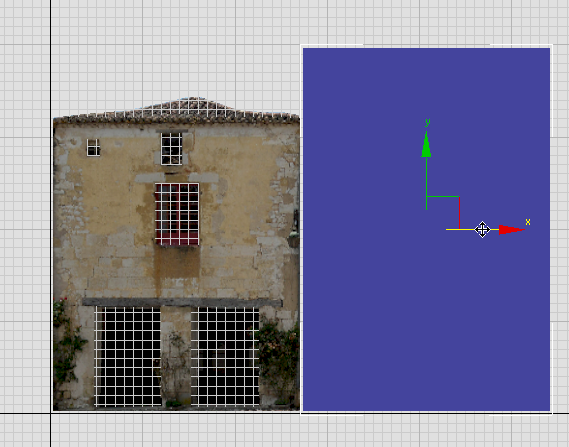
 Hierarchy panel. On the
Adjust Pivot rollout, turn on Affect Pivot Only, then move the pivot vertically so
it is at the base of the Facade4 plane.
Convert
To Editable Poly.
Hierarchy panel. On the
Adjust Pivot rollout, turn on Affect Pivot Only, then move the pivot vertically so
it is at the base of the Facade4 plane.
Convert
To Editable Poly.
 Open the Slate Material
Editor.
mental
ray, and drag the Arch & Design entry to the active View.
Standard, and drag the
Bitmap entry to the active View.
Open the Slate Material
Editor.
mental
ray, and drag the Arch & Design entry to the active View.
Standard, and drag the
Bitmap entry to the active View.
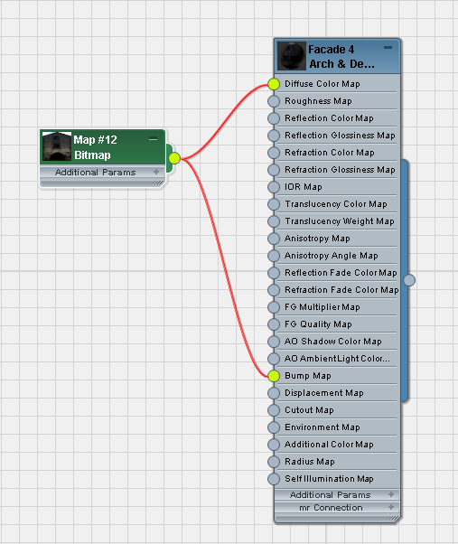
 (Show Map In Viewport).
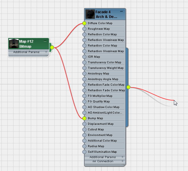
Dragging and dropping is another way to apply a material.
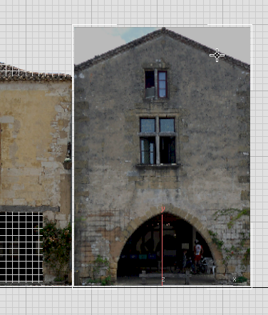
Shaded plane in Front viewport
Close the Slate Material
Editor.
Set up the stack and face-selection color:
 Modify panel.
 (Show End Result) is on
for all three levels of the stack (the two modifiers and the Editable
Poly object itself).
(Show End Result) is on
for all three levels of the stack (the two modifiers and the Editable
Poly object itself).
 (Edge) to go to the Edge
sub-object level. On the Edit panel, click
(Edge) to go to the Edge
sub-object level. On the Edit panel, click  (SwiftLoop) to turn it on.
 (Vertex) to go to the Vertex
sub-object level. Move the upper-left and
upper-right vertices down to match the roofline.
(Vertex) to go to the Vertex
sub-object level. Move the upper-left and
upper-right vertices down to match the roofline.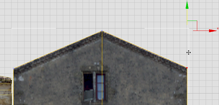
(Edge) to go to the Edge
sub-object level. Click and Ctrl+click to select the two roof
edges, then move them down vertically
a bit to hide the cornice.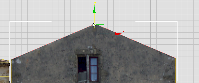
As you did for Facade1, you will add detail for the roof later in this tutorial.
Although we won’t go into detail about creating the windows, you will add their construction edges, as these can help you construct the arch.
Edit panel, click (SwiftLoop) to turn it on
again.
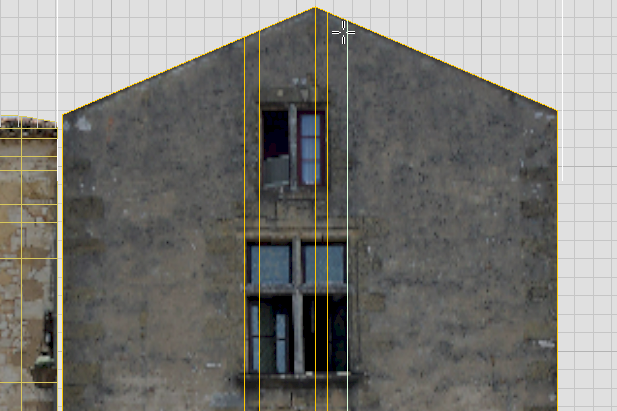
As you work with SwiftLoop, you will notice that the “horizontal” loops are now chevron-shaped, because of the peaked roof. To get true horizontal edges, you need to use a different tool at first.
Edit panel, turn on  (QuickSlice).
3ds Max creates a single horizontal slice.
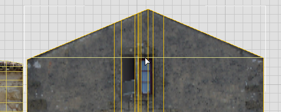
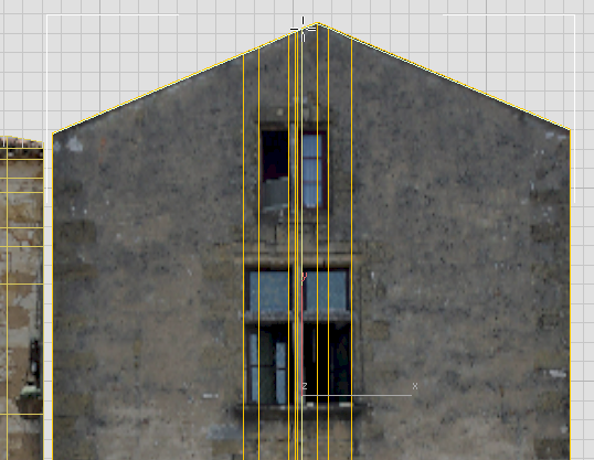
(QuickSlice) again to create
the lower edge of the upper window.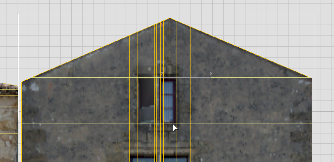
(SwiftLoop) again to create the
horizontal edges for the lower window.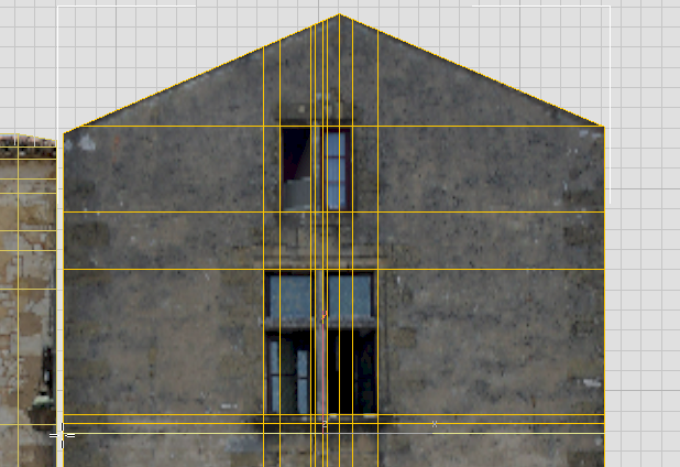
Now you have some of the grid on which you will base the actual arch contour.