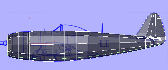
To create the wings, first you make some adjustments to the contours of the fuselage.
 open \modeling\p47\p47_02.max,
 select the P-47.
On the ribbon
select the P-47.
On the ribbon  Polygon
Modeling panel, click Modify Mode, and then click
Polygon
Modeling panel, click Modify Mode, and then click  (Previous Modifier) to go
to the Editable Poly level of the stack.
Polygon Modeling panel, click
(Previous Modifier) to go
to the Editable Poly level of the stack.
Polygon Modeling panel, click  (Show End Result) to turn
it on.
(Show End Result) to turn
it on.
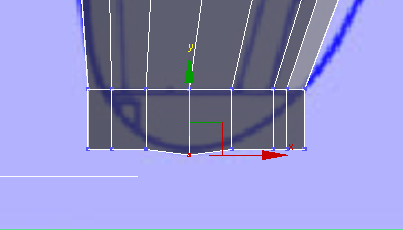
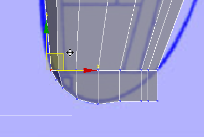
Create the “foundation” for the left-hand wing:
Edit panel, click  (SwiftLoop).
 (Vertex) sub-object level.
Edit panel, activate
(Vertex) sub-object level.
Edit panel, activate  (Constrain To Edge).
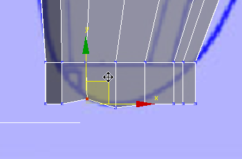
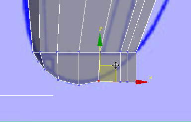
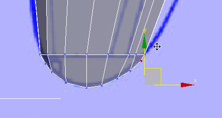
 move vertices vertically
to make a contour that will surround the wing faces.
move vertices vertically
to make a contour that will surround the wing faces.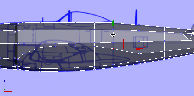
Edit panel, activate  (Constrain To None).
 (Vertex) again to exit the
Vertex sub-object level.
Edit panel, click
(Vertex) again to exit the
Vertex sub-object level.
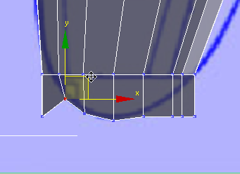
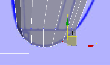
Edit panel, click  (Cut).
(Cut) once again, and as
you did for the stabilizer, add edges from the free-standing vertices
at the leading and trailing edges of the wing to the nearby corner
vertices, to make sure all polygons are quadrangular.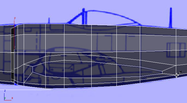
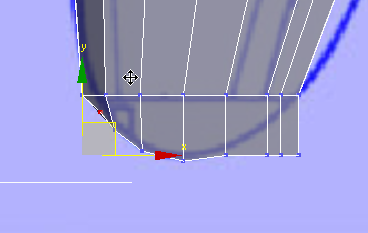
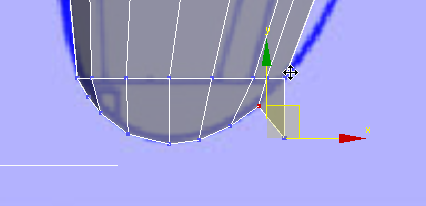
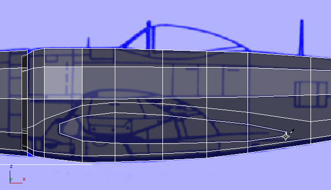
 (Polygon) sub-object level.
Click and Ctrl+click to select the faces that
make up the base of the wing.
(Polygon) sub-object level.
Click and Ctrl+click to select the faces that
make up the base of the wing.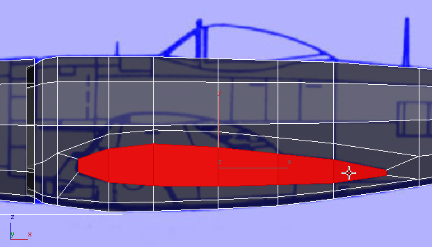
Polygons panel, click  (Extrude). Then drag to
extrude the faces a short distance.
(Extrude). Then drag to
extrude the faces a short distance.
Top view
Align panel, click  (Align X).
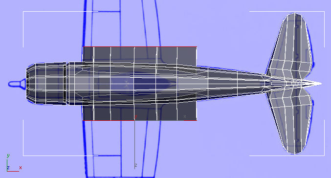
 Scale the faces along their
X axis and move them in both X and
Y so the wing extrusion matches the blueprint image in the Top viewport.
Scale the faces along their
X axis and move them in both X and
Y so the wing extrusion matches the blueprint image in the Top viewport.
scale and move the faces along their
Y axis so the wing matches the blueprint image.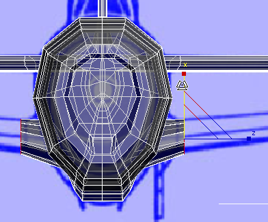
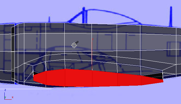
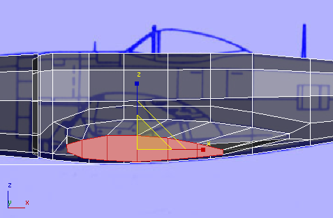
(Vertex) sub-object level,
activate (Constrain To Edge), and move the vertices along
the base of the wing’s upper edge upward along the fuselage (it’s
easiest to select these vertices in the Perspective viewport). Be
sure to activate (Constrain To None) when
you’re done.
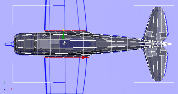
(Polygon) sub-object level, extrude the wing as far
as the seam at its middle.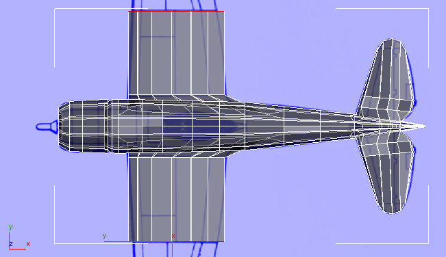
Top view
Scale the faces along their
X axis and move them in both X and
Y so the wing extrusion matches the blueprint image in the Top viewport.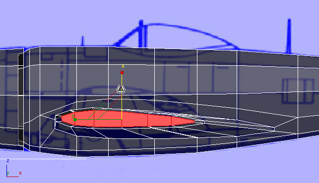
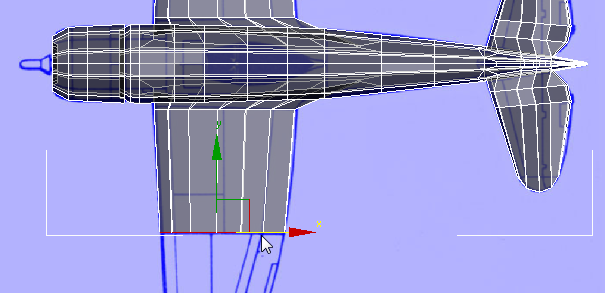
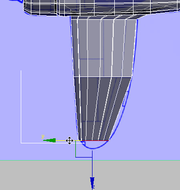
Top view
scale and move the wing in the Left viewport,
so it matches the blueprint image.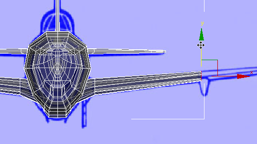
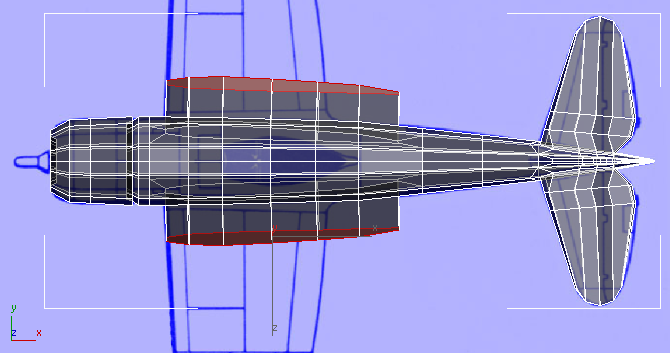
Finish extruding and shaping the wings:
Extrude the wing as far
as the last seam.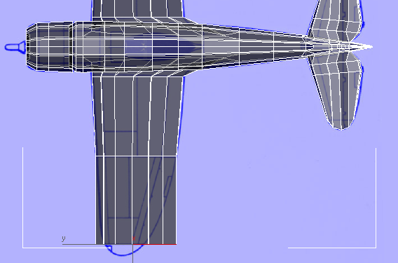
Top view
scale and move the faces so the wing
matches the blueprint image in the Top viewport.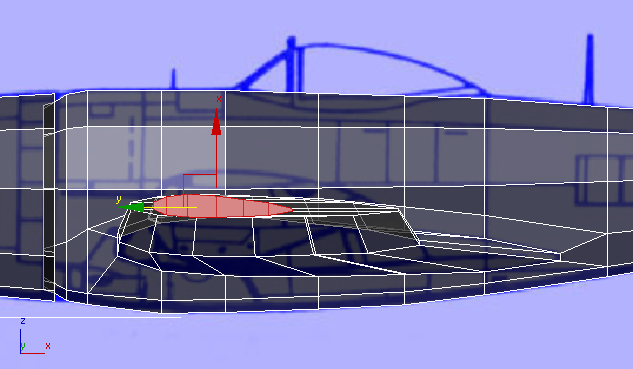
Top view
Extrude the wing again,
this time to the very tip.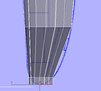
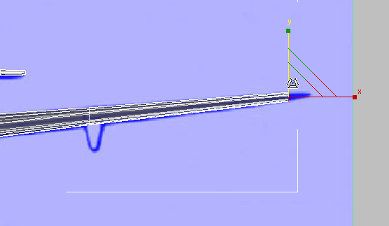
Top view
scale and move the faces to match
the wing to the blueprint image.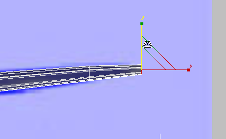
(Vertex) sub-object level.
move them so the curve of
the wing tip matches the blueprint image.