


Creating a Normal Bump
Map
You use Render To Texture to create the normal bump map for the warrior head as well, but you also adjust the cage before you render the map.
 (Open File), navigate to \scenes\materials_and_mapping\normal_bump_map\ and
open warrior_head_lores.max.
(Open File), navigate to \scenes\materials_and_mapping\normal_bump_map\ and
open warrior_head_lores.max.
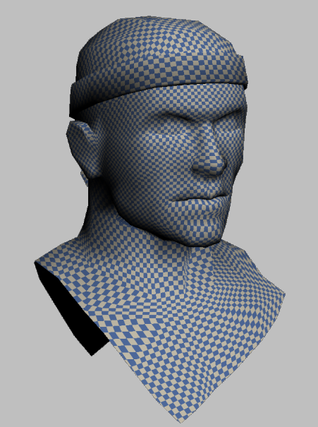
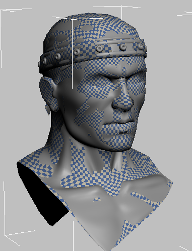
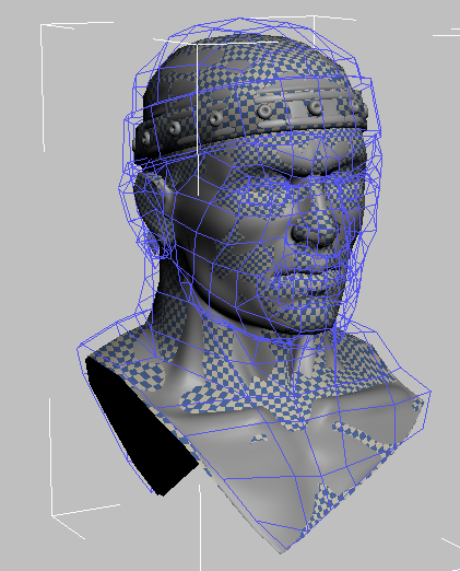
The only visible object is an editable mesh model of the head of a warrior. This is the low-resolution target object, consisting of roughly 750 polygons, to which you will apply normal bump maps. Its surface is smooth, and it has a checkered texture map applied to it. This checker map was used as a visual guide in setting up the texture mapping of the surface. An Unwrap UVW modifier has already been applied.
 Select the model, go to
the
Select the model, go to
the  Modify panel
  Parameters rollout,
and click the Edit button.
Parameters rollout,
and click the Edit button.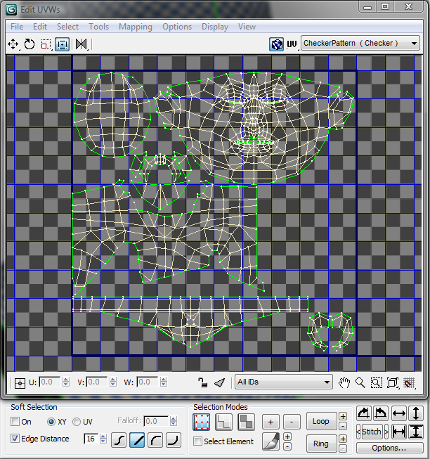
3ds Max opens the Edit UVWs dialog, which shows how the Unwrap UVW modifier has already been applied to the target object, and how the texture coordinates have been mapped to the surfaces of the model. This layout was designed to facilitate painting, which can be necessary for “touching up” texture mapping.
 (Face Sub-Object Mode).
In the main window, select geometry elements to see how they correspond
to the model in the Perspective viewport.
(Face Sub-Object Mode).
In the main window, select geometry elements to see how they correspond
to the model in the Perspective viewport.  Close the dialog when you
are done.
Close the dialog when you
are done.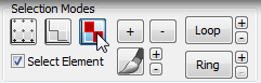
In order to extract the high-resolution information from the source model, you will now need to merge it with the low-resolution version.
Merge the high-resolution model:
 Application menu, choose
Import Merge,
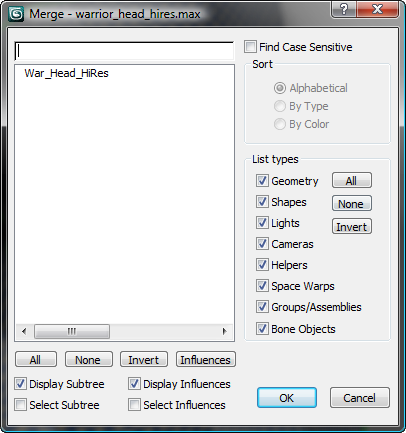
and on the file dialog, navigate to the folder that contains your
scene files. Select the scene that contains the high-resolution
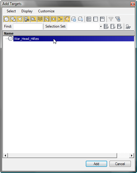
model warrior_headhires.max, then click
Open.
Application menu, choose
Import Merge,
and on the file dialog, navigate to the folder that contains your
scene files. Select the scene that contains the high-resolution
model warrior_headhires.max, then click
Open.
The two models are now visible. Both are the same size and are precisely aligned.
select a non-checkered part of
the head, right-click, and from the quad menu choose Isolate Selection.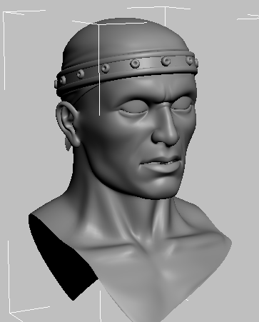
This model, at approximately 96,000 polygons, shows a much greater amount of detail.
click a checkered region
of the model to select the low-resolution model.
To make sure you have the low-resolution model selected, check that the Name And Color rollout displays War_Head_LoRes.
Now you will proceed to create the normal bump map based on the high-resolution model.
Set up Render To Texture (RTT):
To generate the normal bump map, you will use the Render To Texture tool.
Render To Texture.
General Settings rollout Output group, define
the output path where you want to save the diffuse and normal bump
map textures you are about to create.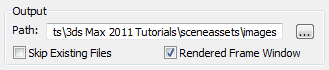
By default, the output is saved in the \sceneassets\images folder of the current project, but you might want to specify a different storage location.
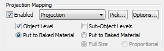
Projection Mapping group,
turn on Enabled, then turn off Sub-Object Levels, since no sub-selections
exist in this particular model.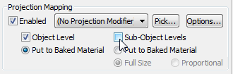
The drop-down list in the Projection Mapping group has changed from (No Projection Modifier) to Projection, indicating that a new Projection modifier has been placed on the stack for War_Head_HiRes.
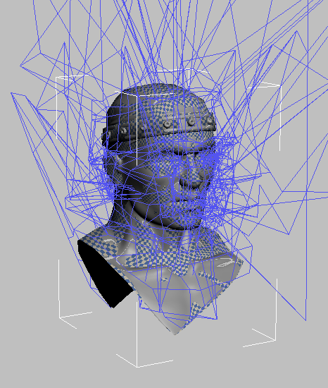
Also, a rough wireframe cage appears around the high-resolution head object in the viewport. The cage shows a considerable amount of irregular geometry, but this is usual when it is first applied. The problem is easy to correct.
Cage rollout, click Reset.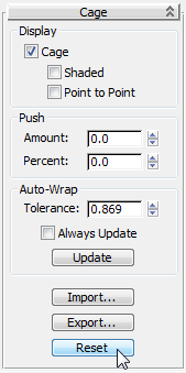
The cage resets itself to fit tightly around the target low-resolution model.
The shape of the cage is correct, but it is important that the cage fully encompass the source high-resolution model. Where the source geometry lies outside the cage, the result will be ray intersection misses, which in turn will cause flaws in the normal bump map.
Push group, set Amount to 1.1.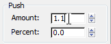
After the value is applied, it resets to 0.0 and the cage balloons outward slightly so that the entire War_Head_HiRes object, with all its bumps and protrusions, fits within it.
Objects To Bake rollout Mapping Coordinates
group, choose Use Existing Channel.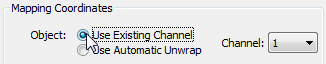
This is where you specify that you want to use the pre-assigned texture-mapping coordinates you viewed at the beginning of this lesson, rather than letting 3ds Max create new texture-mapping coordinates on the fly.
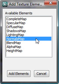
A new NormalsMap entry appears on the Output rollout of the Render To Texture dialog.
Target
Map Slot drop-down list, choose Bump, then click the 512 x 512 Width/Height
button, which sets the output size to 512 by 512 pixels.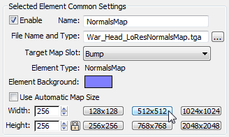
At this point, you have defined all the basic elements and settings for generating a normal bump map.
Render and fine-tune the normal bump map:
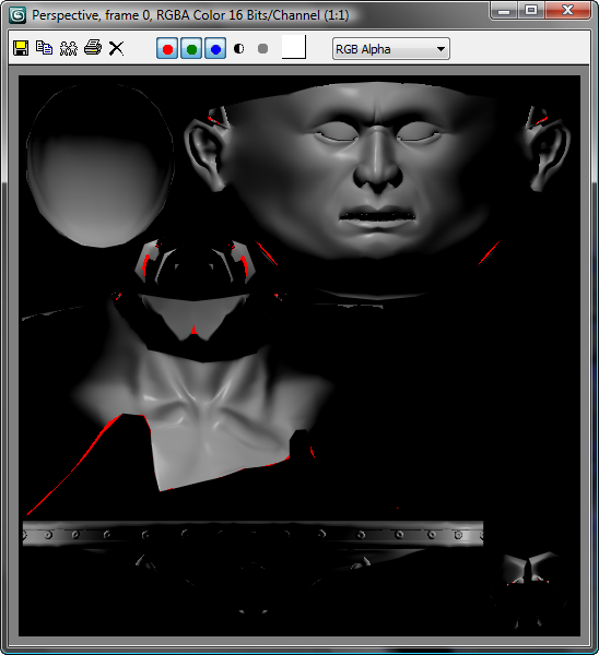
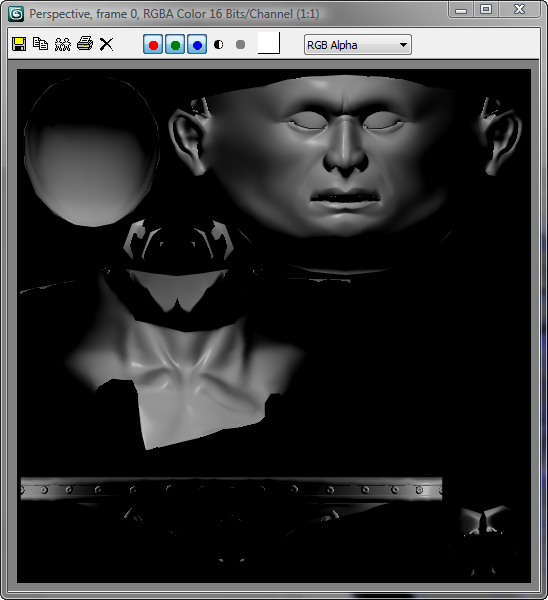
The rendered map shows an unwrapped diffuse rendering of the high-resolution model. Assorted red patches are visible, indicating where the bump map projection rays did not properly capture the underlying geometry. This is because the cage created by the Projection modifier did not completely cover the high-resolution model in these spots.
This would create problems if you applied the normal bump map to the low-resolution target. You will resolve this problem by applying neutral normal values to these red patches so they blend with their surrounding areas.
Objects To Bake Projection Mapping group, click Options
to display the Projection Options dialog.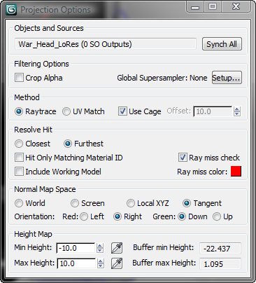
close the dialog.
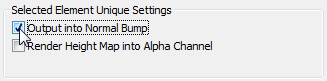
With Ray Miss Check turned off, the red patches in the rendered normal bump map will be replaced by a neutral blue background with a normal value of 0, a value that will permit the regions to blend effectively with the normal map that will be created.
Click Overwrite Files when you are prompted to overwrite the previous rendered file.
The rendered result shows that the previous ray misses now appear as black, the neutral element background.
Now you will take a look at the actual normal bump map image file to see the blending result.
View Image File. In
the file dialog that displays, navigate to the image file location,
which by default is \sceneassets\images.
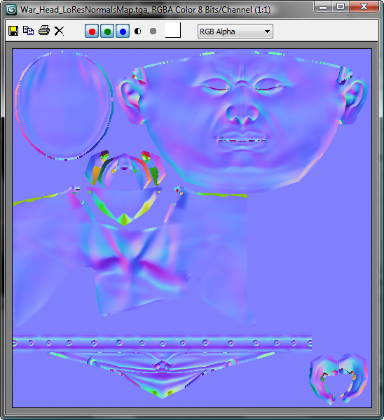
The blue channel conveys vertical depth information, and the red and green channels enhance this information by providing a direction vector for the normal orientation of the surface at each point. This conveys more information than an ordinary grayscale bump map.
Close the normal map image.